
Nothing serious, trying to catch up on some loose ends. One of the fun things I tested today was seeing how low my input voltage can go before the output (5 Volt) collapses.
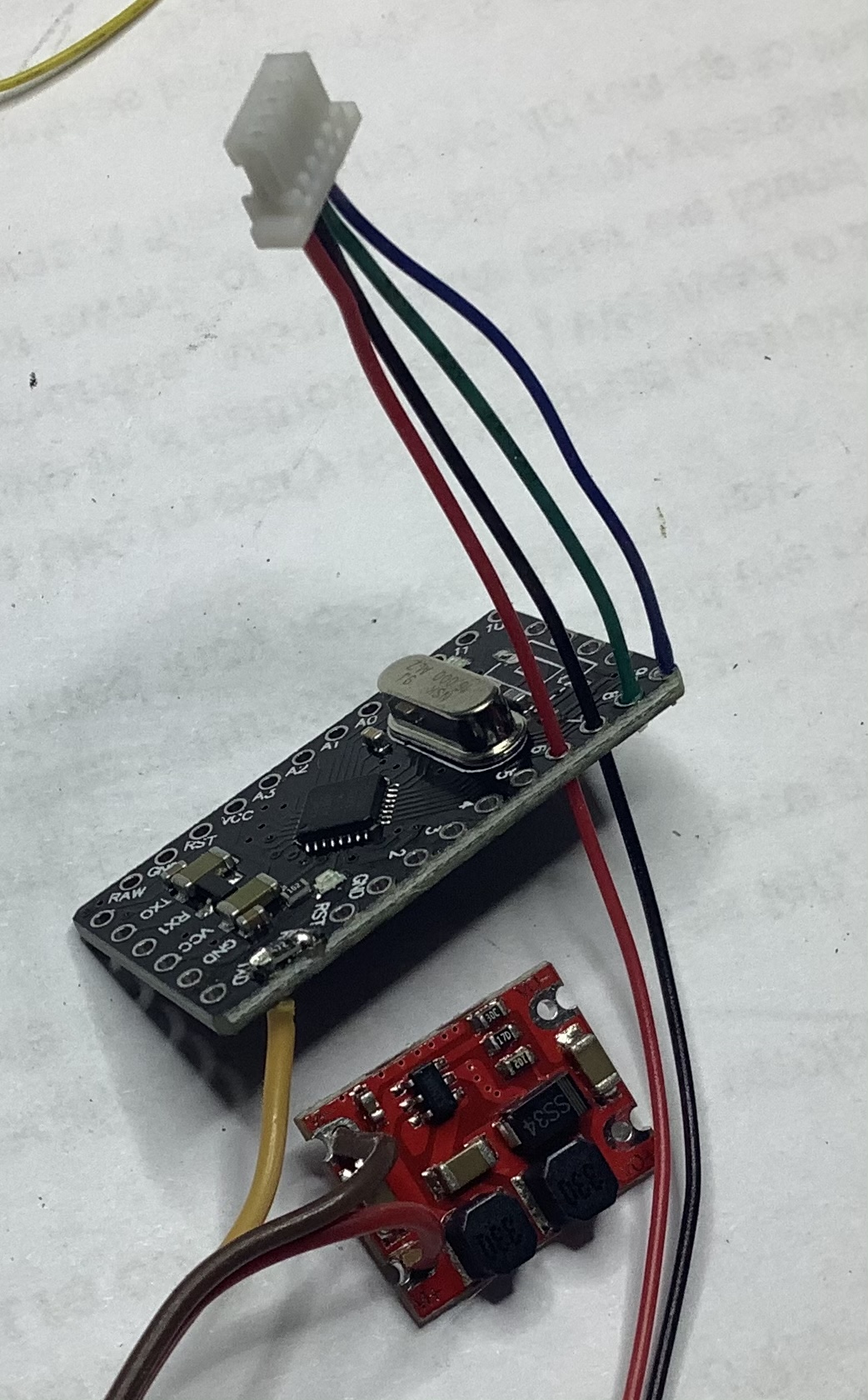
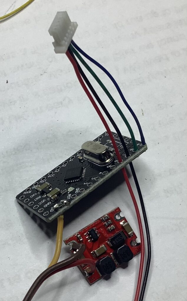
The background to this is that initially when building Jeti sensors, I used step-down converters to allow the use of 2S battery systems. Some were failing very quickly, and often suffered from brownouts. Therefore I searched for a better solution. Buck-boost converter technology is old hat, just finding suitable ones in a small package was the challenge. I’ve been using these for a while now, with no problems.
In this test I wanted to see how low I could go with the input. As expected, the receiver works to about 3.4Volts, then it complains. The buck-boost converter keeps producing 5 Volt for the sensors, so they are happy.
It’s nice to see that the input range for my Jeti sensors is from 3.4 to 8.4 Volts.
(I should also try if they can handle a DLG. Even 2 if needed. That’s another project.)
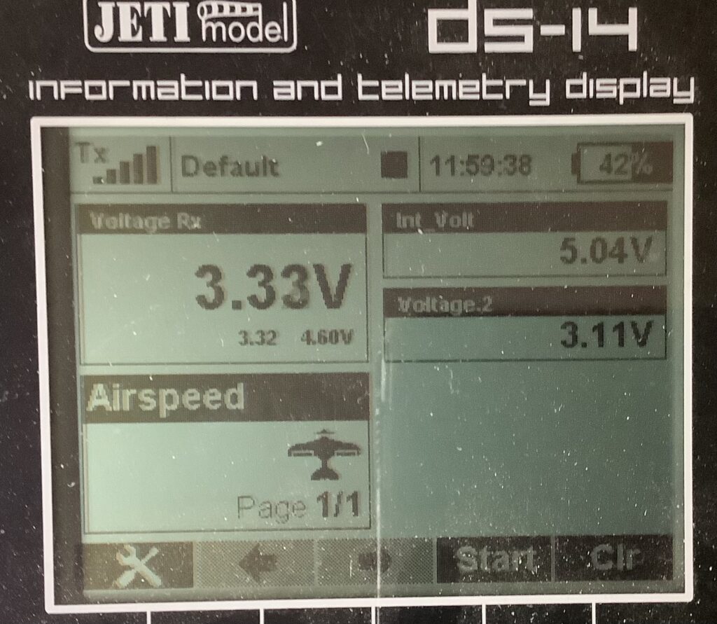
The voltage measured by the Receiver is slightly off, it’s really 3.4 Volts, the measurements for the other inputs are not calibrated yet. I used 10% resistors, so not exactly precision stuff. Will work that out later. This was more about seeing if I kept the 5 volts going. And it does. At least I have a picture to show that now.