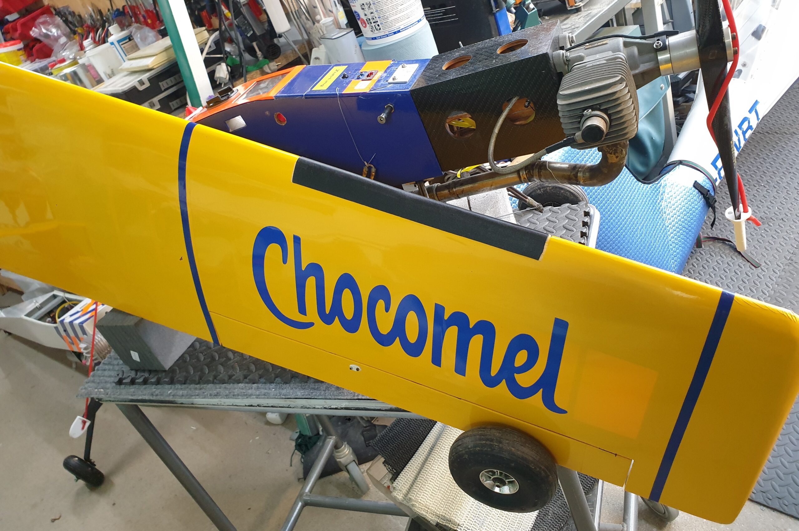
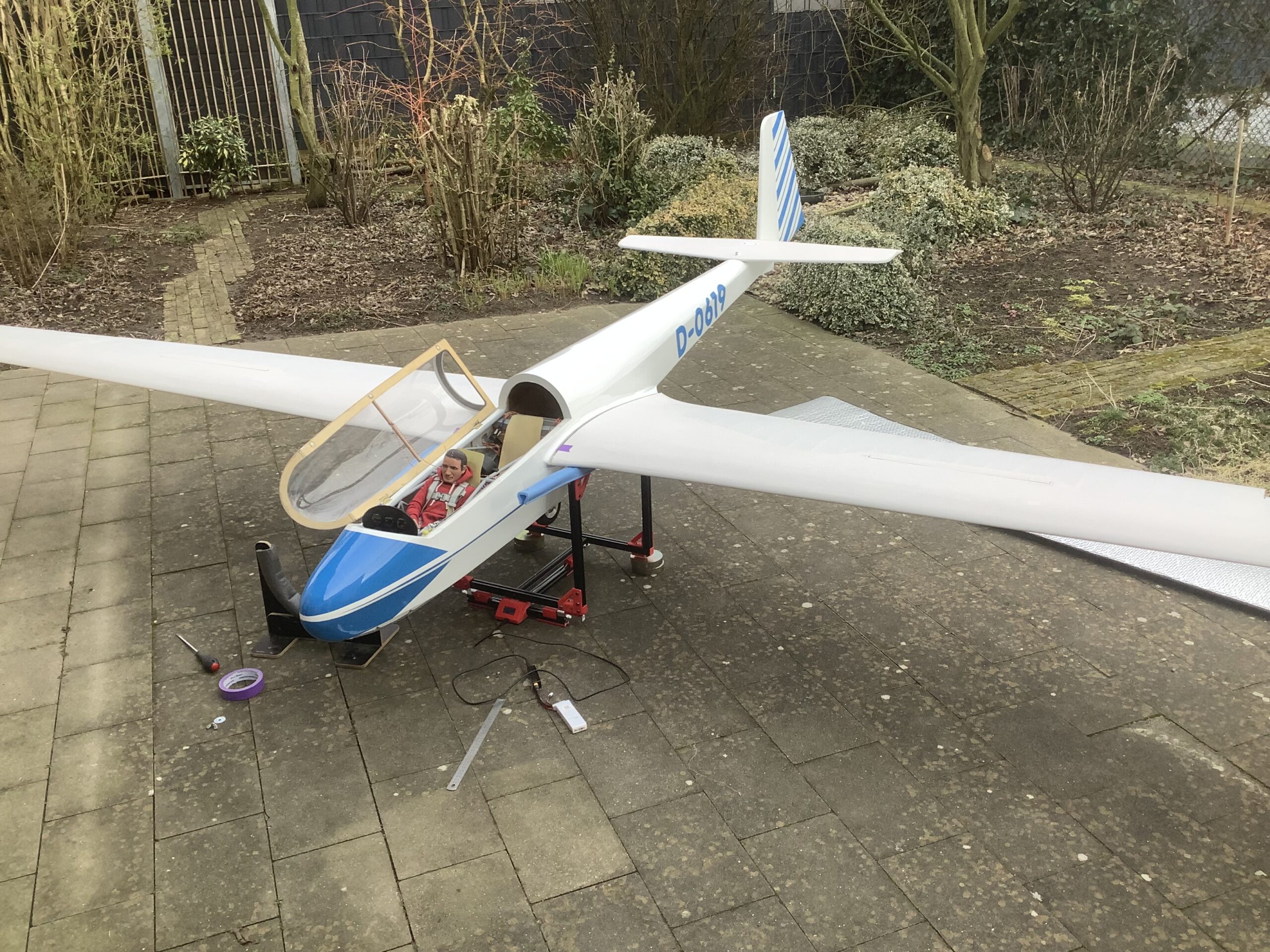
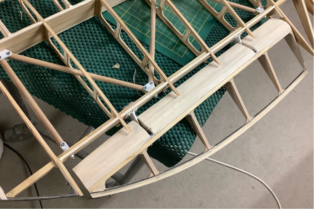
Kees

Surpise, surprise, it works!

 Flarm, Tracker  Comments Off on Surpise, surprise, it works!
Dec 182020
 

After building a nicer box for the electronics, I used my Acrowot as the test-bed of choice, the motor mount is loose, the battery is 7 years old, but hey, just enough oomph for a test. Anyways, looking at the data, I am very happy. My receiver on the shed even picks up the signal when I am in the pits, I had not expected that. Higher up is no surprise of course. The signal is much stronger than what I usually get from Real Planes. (Our field is only 1.3 km from my receiver. I do catch full size planes as far as 30 km away, when I have a clear line of sight.)

There’s more info about the story here.

Ye ol’ acrowot, forever going strong!

So, now it’s a matter of putting this contraption in the bigger planes, and get some more data. Don’t forget this is built for full-size aircraft, to allow them to spot nearby traffic. When you see 1900 foot/minute ascends of this tracker, you know it’s either a UFO or a model-airplane! The number of data points is relatively low, but enough to make them big ones know I am there! I took this image while in the pits, plane on the picknick table: still 4.5 dB signal, even though there are buildings and trees in the way. Speed is of course determined by GPS readings. Even when stationary, it will show movement. (All GPS-es do this, usually it’s the software that filters this away, but we likes the real stuff, not all smoothed)

Lots of wigglies, after 3 flights, my battery was empty.
These are all data points from all aircraft since beginning sept 2020

As you can see on the heatmap above, lots of data when I was in the pits, sorting out my ailerons (reversed) motor (reversed). I also noticed that the fixed motor mount is more of a flexi-mount at the moment. It explains the funny behavior of the plane at full power. Anyway, not worried about that, that was not part of the exercise. Below is some raw data: (first number is time in GMT, then coordinates, altitude, rate of change, acend/decend, heading, and some more stuff relating to reception of the signal.)

122704: [ +51.86655,  +6.15268]deg     3m  +5.3m/s   3.2m/s 341.7deg  +0.0deg/s Dm4 03x05m Fn:00_o_ -0.86kHz  4.5/20.5dB/2  1e     1.3km 185.1deg  -0.8deg    !   * 

3 meter altitude, 20.5 dB signal!

122207: [ +51.86728,  +6.15048]deg   103m  -3.9m/s  20.0m/s 059.7deg  +0.0deg/s Dm4 03x05m Fn:00_o_ -0.76kHz 13.5/27.0dB/0  0e     1.3km 192.3deg  +3.5deg  

and 100 meter, 27 dB. I honestly had not expected those numbers.

And from GliderRadar more raw data: even going down in a hurry (2000 ft/min) it tracks nicely. The highest altitude recorded was 784 ft, (239 meter) which of course is also nicely shown on glidertracker.

12/18/2020 1:27:37 PM+01:00: FLR66052A>OGFLR,qAS,Elten:/122736h5152.08N/00609.05E'071/037/A=000285 !W53! id3666052A -1979fpm +0.0rot 11.2dB -0.9kHz gps3x5

After seeing this, there is no need to try to build a better antenna, these stubs do rightly!

And just to explain why I did all this: The picture below tells the story, a full size heli, flying at 93 meters, at well over 100 km/hr, where I was a few minutes earlier. Next time he does that, he will get lots of alarm bells in his ears!

With this subject out of the way, I can start making snow for Xmas again! (More sanding wings…)

I hear someone thinking: If I wanted to use something like this, but I am not near a groundstation, would that work?

I am sure I could use a mobile receiver setup, and link to ye interwebs through a GSM phone. The amount of data is not high, only what the receiver sees from passing full size traffic and whatever you fly yourself. Sounds like a project, most of the stuff is looking at me.

  • Raspberrypi, connected to GSM as hotspot: easy
  • RTL-SDR dongle: got it
  • Antenna : done, it does not have to be high, since you only want local traffic.
  • Some Battery for power: take your pick
  • But if I don’t have a GSM/Signal? You never worried before, just keep on flying!

Sounds like a fun project, lets do it!


Could not let it go..

 Flarm, Tracker  Comments Off on Could not let it go..
Dec 152020
 

It’s one of these things I knew I could fix, if only I would just concentrate. I’m talking about my almost nose to nose encounter with that heli-boy a while back. It sure did scare me, tell you that! Anyway, we now have the Technology, so next time, he will see me/us.

The Technology is a so called tracker-device that is used in more and more full size air-planes. It’s an open source project, so the costs are peanuts compared to the existing equipment. Within the protocol there is a type of plane ‘Drone/UAV’. For my purpose that’s close enough to the truth.

It’s basically a transmitter that sends it’s location to the nearby receiver on top of my garage. The location is then shared over the Interweb, and all planes that have FLARM receivers, will see the position and hopefully take action. (very short, very much simplified version) (See OGN for an introduction)

Since the receiver is only 1300 meters from our flying site, I hope to be able to pick up the signals from the transmitters. If not, we’ll sort it!

So with some luck and dry weather, I hope to try this for real in the next few days/week/whenever.

Busy busy making dust..

 ASK21  Comments Off on Busy busy making dust..
Dec 102020
 

I’ve been sanding and plastering and sanding more and then some more and still there’s more to sand. All in an effort to make the ASK21 wing profile as accurate as I can. It’s a real effort, and very time consuming.

The root section is the worst, especially the nose of the profile was not even close. I do understand the foam cutting process very well, and know where the problems are. Especially in a long tapered wings.

Anyway, every small step is one step closer to being finished.

Notice my super long sanding bar, it is a real help!

The tip section is sort of ok, I can work with that.

3D printer woes..

 3D print  Comments Off on 3D printer woes..
Nov 192020
 

My bed was giving me problems. For ABS you need a bed temperature of at least 100 C. 110 is better. In the original design, all electronics are in the base of the printer, but with a 110 degree bed things were getting too comfy. That resulted in random interruptions of the print, even with added fans in the bottom Since I ran out of PLA and ASA filaments, and only had ABS left, I decided to fix the problem properly. So I stripped everything and rebuild the whole thing. It was only a weeks work, but I am pretty confident things are working better now.

Because I rebuild the bed, it also meant doing all the lovely calibrations from scratch. Anyways, we are back to printing, and at this moment the blinking lights are blinking as they should.

So now I can print a few brackets and bits to finalize the upgrade. Another job done, and hopefully lots of happy ABS parts to come.

Still need to add the camera again, and some interior lights, and a door to keep all the precious heat inside the box, but we’re getting there!

Playing with electronics again.

 Arduino  Comments Off on Playing with electronics again.
Nov 122020
 

Nothing serious, trying to catch up on some loose ends. One of the fun things I tested today was seeing how low my input voltage can go before the output (5 Volt) collapses.

The background to this is that initially when building Jeti sensors, I used step-down converters to allow the use of 2S battery systems. Some were failing very quickly, and often suffered from brownouts. Therefore I searched for a better solution. Buck-boost converter technology is old hat, just finding suitable ones in a small package was the challenge. I’ve been using these for a while now, with no problems.

In this test I wanted to see how low I could go with the input. As expected, the receiver works to about 3.4Volts, then it complains. The buck-boost converter keeps producing 5 Volt for the sensors, so they are happy.

It’s nice to see that the input range for my Jeti sensors is from 3.4 to 8.4 Volts.

(I should also try if they can handle a DLG. Even 2 if needed. That’s another project.)

buck-boost converter is the red thingy.
need to calibrate the voltages, but it gives you the general idea.

The voltage measured by the Receiver is slightly off, it’s really 3.4 Volts, the measurements for the other inputs are not calibrated yet. I used 10% resistors, so not exactly precision stuff. Will work that out later. This was more about seeing if I kept the 5 volts going. And it does. At least I have a picture to show that now.

Change of format

 Acroduster  Comments Off on Change of format
Oct 262020
 

I’m going to make one post a week, and add all the stuff I do in this post. Unless I change me mind.

I wondered how long I have been working on this: looks like first metal was cut in June 2019. Not bad.

Before going too far I thought it would be a good idea to see if the wing still fits. Since it is a nice pleasant day, it was a good moment for a selfie.

using this image to see if things are square.

There is some work left on the aileron, once that is done, I’ll do the root rib. Somewhere in between I also have to build the servo/linkage/bellcrank.

Sounds like another fun week coming up!

challenging to get the shape right
this is not the same type of plane, but of similar origin/construction

 Posted by at 11:07 am  Tagged with:

Ailerons again

 Acroduster  Comments Off on Ailerons again
Oct 182020
 

Some of the drawings are not to scale, which is no problem if you build the full size version. A few important ribs are drawn full size, and from there it is easy to find the missing dimensions. Because the dimensions on a piece of paper are very hard to determine accurately, I found I needed to start measuring from the full size ribs on paper. From there it is easier to scale everything back to 1/3 scale.

There is a drawing with dimension to create the curved trailing edge, but there was no reference to the distances to the spars. Anyway, doing the extra work was not difficult, just time consuming.

dimensions for full size
wing goes down
this also gives the max deflection of the aileron.

Still trying to work out the trailing edge. It’s a 1″ alu shaped piece. Since it is not available any more, people use a traditional wooden one. However, since the ribs are quite small at that point I’m still not sure how to attach it. One option is the method using gussets on top and bottom.

trailing edge with some carbon for support.

Build support for the trailing edge and aileron spar. This should keep things lined up. Next step, attaching the root ribs to the trailing edge and build the aileron ribs.

While I have the router setup for cutting wood, I’ll do the nose templates for the ASK21 wing.

lots of filling and sanding to get to this shape!

Lots of fiddly bits, progress seems slow, but it’s raining, so who cares. Getting the aileron spar dimension correct is what is holding me up.

I am going to cut some negative ribs to slide over the aileron ribs, so that the trailing edge ends up where I want it. Even with the jigs on the building board I am not getting the right alignment results. Which probably means there is an error somewhere.

Sometimes you miss the obvious: there are no capstrips on the aileron ribs! that makes things easier. Tomorrow is another day, another challenge.

oh dear, is that not dangerous?
nah, get’s the job done. (4x4mm with 2 mm slot)
and some fun with the wingtips

one day I’ll turn this into a readable story, now it’s my diary!

That’s it for this week!

Ailerons bits

 Acroduster  Comments Off on Ailerons bits
Oct 102020
 
wing side part of aileron hinges

The ailerons contain quite a lot of parts. Apart from hinges, there is also a link to drive the top wing aileron. And the link to the bell-crank that is connected to the control stick.

now add some brass bearing bushings
a bit of riveting and we’re done

I started using a 1.5mm bit for cutting, it allows a higher spindle rpm, and better cutting of holes. Using the 2 mm bit to drill the holes was not really a good idea. Milling cutters are not drills! Also had to reduce the cutting depth per pass to max 0.3mm. A cnc router designed for wood does not have the stiffness do do any more. (At least mine does not) So with these settings and mild steel, things go great. The material for these parts is stuff from the local DIY shop, supposedly 1 mm thick. It’s more like 0.9, but I’m not complaining.

Drawings show full size part.

Anyways, just for reference: The original material is listed in ‘Standard Aerospace Extruded Shapes’, these ones start life as ‘AND10136-2403’ (AND stands for Army-Navy-Drawings.) It’s an aluminium T-profile to you and me. Finding out how it is supposed to be made makes it easier to make something that ‘will be close enough’.

bearing holes are drilled 2 mm, might go to 2.5 in the final assembly.

The result after paying close attention to alignment and clamping. This will do. Make a few more and on to the next step!

The reason I have 2 pcs joined is that I use 2 mm drill bits stuck through the outermost holes to align the blanks before bending. This ensures (hopefully) that that both end up equal.

 Posted by at 6:54 pm  Tagged with:

Cutting more metal

 Acroduster, CNC  Comments Off on Cutting more metal
Oct 082020
 

The truss tubes provide the for/aft strength of the wing. Since these are in place now, I continue with the ailerons horns and linkages. Once those are done, I can start on the aileron and trailing edge. Then only repeat 3 more times. Funny how some of the ribs look skewed, but it’s honestly the camera, real life is perfect. And that second nose rib from the left, even that is where it is supposed to be!

plans show full size, mine are mysize. 2024-T3 is what we used to call dural.
using cheap dowel for now.
0.85 euro dowels or 8 euro tubes.. I’ll think about it.

Making the aileron attachment points is next. Real life and drawing do not always match, but it’s close. (The base of the horn is approx 1 mm too high. Of course I should have measured that beforehand.) There will be a brass bushing in the big hole, and I will have a look if I can find 2 mm rivets. If not, the 2 mm bolts will do. Might put a bit of solder on the back, so that even when the rivets do nothing, it will still be stronger than needed. And I need to work out a clamp to allow accurate bending of that flange.

Aileron hinge: first trial part, forgot one ‘cut on the outside of the contour’ section. For the rest acceptable.

 Posted by at 7:05 pm

ASK21, lets start

 ASK21  Comments Off on ASK21, lets start
Oct 072020
 

I’ve been looking at it for too long, so let’s get going. As always, first things first. The wings are what keeps us up there, the rest is only there to keep the pilot dry and comfy.

taking the glider by the tail…

The kit I have was produced by Heinz Maassen Flugzeugbau. (I believe Heinz passed away early 2015) ….Die Maassen ASK 21 resp. später Mario Hermani (MH)-Flugmodellbau wird jetzt durch Jetisfaction produziert und vertrieben I read somewhere. However Jetisfaction is gone too. What stays are the gliders.

Long ago, Onki wrote a story, Another one here , More words.

Wings are of a typical foam/abachi construction with ample glass and carbon under the skin (I hope).

As copied from the wing root.

However, I think the trailing edge of the wings can be improved upon. So we starts the process by figuring out the wing profile. I don’t have a 100% guarantee I am right, but it looks like I have of Helmut Quabeck profiles.

To check I enlisted the usual suspect: Profili to import the profile coordinates (found at the top of the page on Helmut’s website), do the usual fake wing construction in Profili, print the ribs on a piece of paper and see how close we are. Main profile is close. And as already determined, the trailing edge needs work. Normally I would cut a plywood template, but I don’t want to mess up the router at present, I am still producing metal chips)

The red pen mark is what I have now.

Sanding the top of the wing down to the glass skin is easy enough, the bottom part is where it gets interesting. You need to keep the hollow bit accurate. Maybe I could make a printed sanding block? I do have the coordinates after all.

works! just had to add a steel wire, because the glass eats the plastic real fast.

With the knowledge of the profile, I can also print nose templates, the nose part is round-ish, but not the way a profile should be, that much I can say.

In the meantime I am trying to learn another CAD program, one that is a bit more up to date AND can talk to my router. Getting more difficult as the years go by. (not so much the learning, but trying to make old hardware work with new software)

This part was supposed to be a quick ‘slap on some glass and it will be ready’. You know by now, if I spot a challenge, I will go for it!

nose templates.

I think that I will sleep better if I change the leading edge. Will check the other wing tomorrow and decide then.

 Posted by at 6:07 pm