
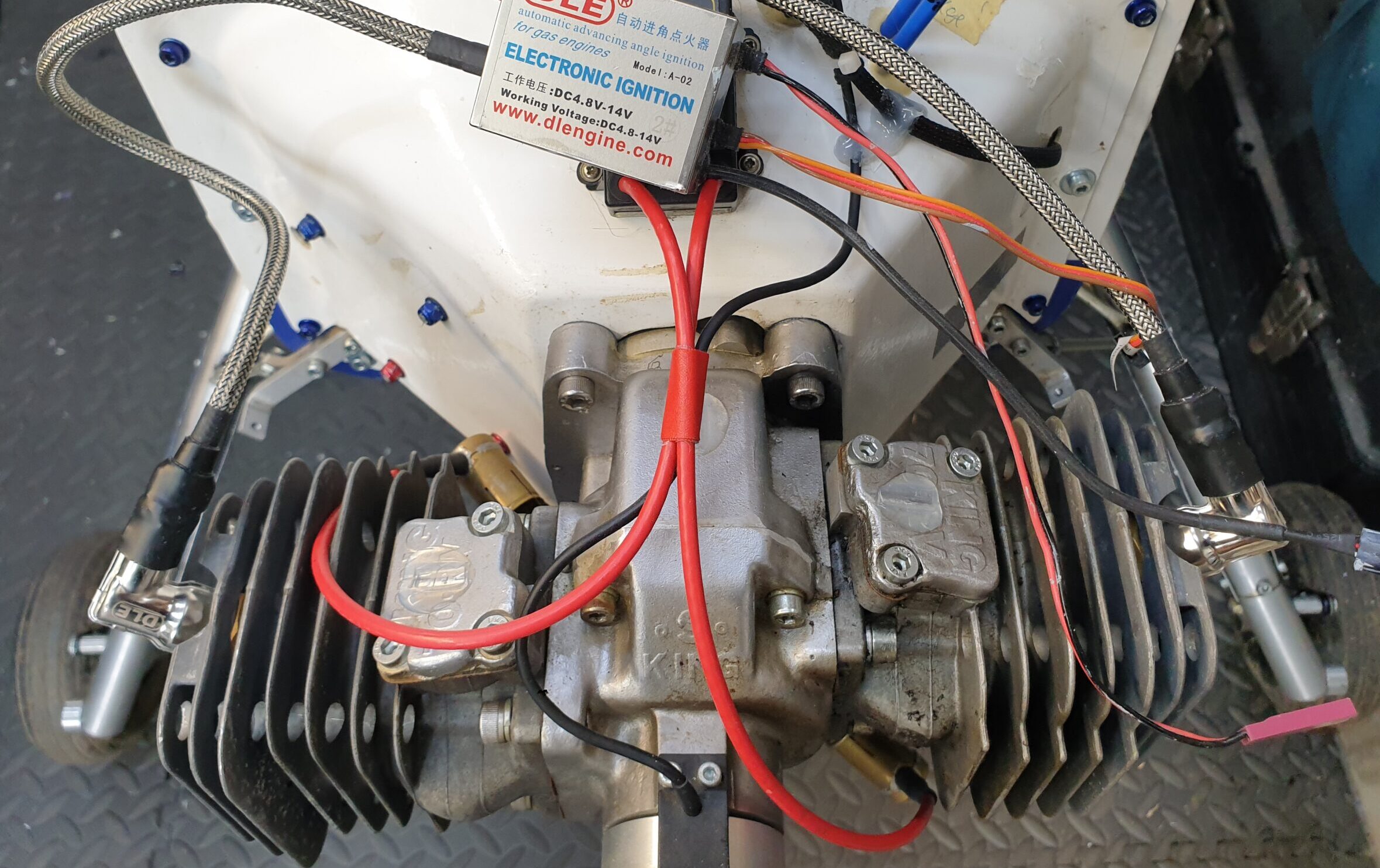
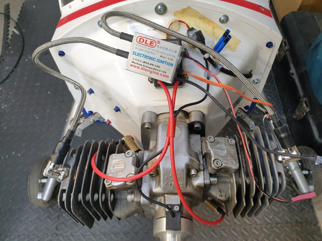
This week I had the pleasure of finally (famous last words) sorting out a Wilga with a King140. For quite some time the engine would not start, then run irregularly, then on another day it was fine, in other words, it was all over the place. Of course I approached the problem with: 95% chance it’s something to do with the carburetor, let me change diaphragm and clean it. Diaphragm was definitely not good, but no traces of dirt were found inside the carburetor. Of course the joy of the machine is, that every time you want to do something to the engine, you spend a good 2 hours mounting or disassembling the engine from the air-frame. After carburetor cleaning: same behavior, starts very briefly and dies. Ok, from the remaining 5%, I bet 90% chance it’s the ignition. Smart decision, because that requires some Major Thinking. The King140 has a Becker Ignition, but worse, it has a special sensor adapter, and the magnet is mounted the wrong way, compared to ‘standard RCXel ones’. Ok, nothing a 3D printer can’t make. Spend another unspecified amount of hours creating and mounting the sensor with ignition. And low and behold, Sparks are being generated. But, try as I might, same behavior as before. It starts if you flood the carb, and then dies.
We are now down to the very few last options. Lets take everything apart again, and really, I mean really look closely at anything that has to do with getting the fuel into the crankcase. The King140 has a rotating disc on the crankshaft, that allows fuel into the crankcase when the pistons rise. And like most 2 strokes, there is a hole from the crankcase that aligns with a similar hole in the carburetor. This allows the crankcase pressure (on the down stroke) to drive the diaphragm in the carb.
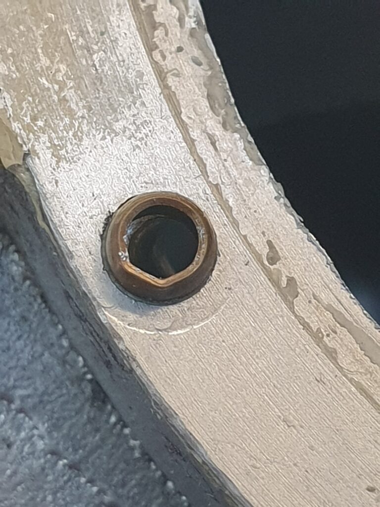
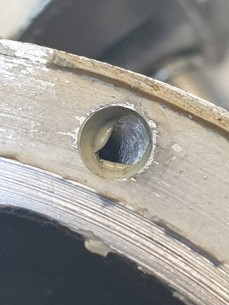
So, since the rear cover is held onto the crankcase with only 6 screws, it was easy enough to just have a peek inside the crankcase and see what lives there. The crankcase has a small 3 mm steel tube inserted into the transfer hole. The inner diameter is 2 mm, so, insert a 2 mm drill-bit and make sure the hole is really open. By rotating the crankshaft (and thus the disc) you can actually see inside, and see the drill-bit I poked through. Now look at the other side of the backplate, where the hole goes all the way through to the location where the carburetor is mounted. WTF? I see some gunge, that I don’t want to see in the little hole! This is also a 2 mm hole, so twist the drill-bit in, and surprise, a whole load of silicon rubber, that should not be there!
So, in hindsight: When the motor was assembled, some eons ago, the assembler used some packing-gunge to seal the backplate/crankcase interface. Now I am sure the assembly manual said ‘apply sparingly!’. Alas, fate decided to let a small amount find it’s way into the transfer hole. Not enough to completely block it at once, but enough to cause issues in later life. There is also another reason why that little tube is inserted into the crankcase, it allows you to spread a very thin layer of sealant on the mating surface, without it going to places it should not. Yeah, it is all easy when you find the problem.
All good stories have a happy end, and after assembling everything one more time, reinstalling the original ignition, it was time for final test. (this a a whatsapp version of the video, I should have saved it beforehand.)