
I received some chips last week, they are to be used in a VarioGPS unit for Jeti. I’ve build around a dozen of these things now, and so far I have had no real issues. So what happened?
As always with stuff from ‘the east’ you never know what you get. But I am jumping ahead.
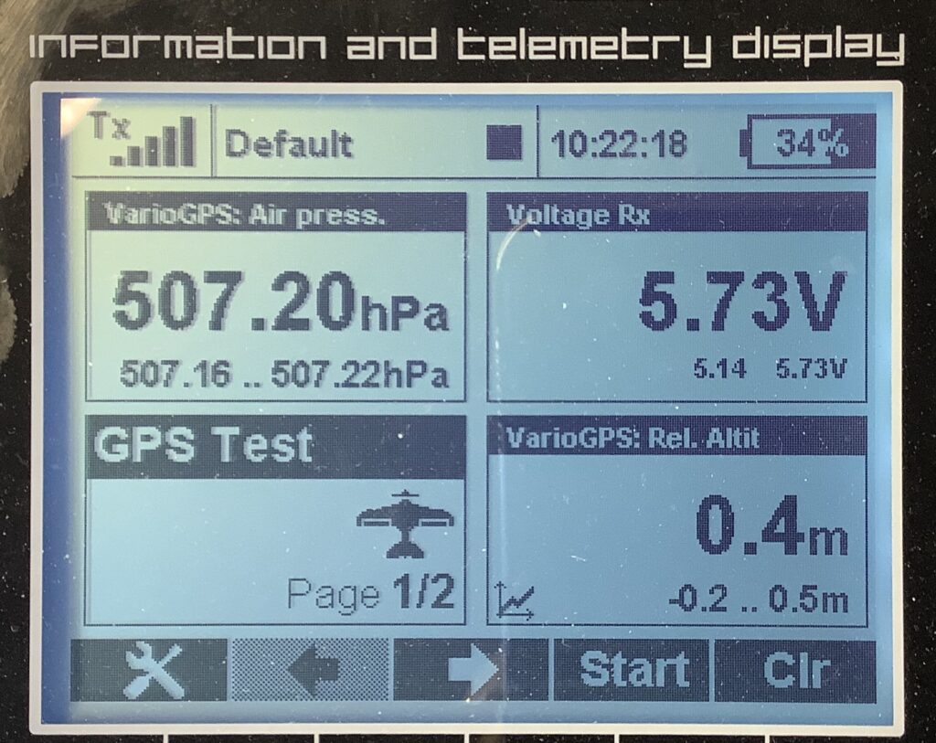
With a fresh cup of coffee and a hot soldering iron, fun is to be had. First load the firmware on the Arduino-Nano. Yup, done that a million times. Only this time my usb cable is bad. Ah well, after last weeks mains cable to the router spindle, what is to be expected? Somebody trying to keep me on my toes? Anyway, carrying on regardless. Code loaded, and the first one assembled. No GPS reading? And the air pressure is only 507 hPa? (Exactly half what it has to be.)
Ok, back to basics. Of the 10 GPS modules (them expensive ones) 9 are good, the one I used is bad (for now, maybe I can revive it).
But that altitude problem turns out to be a Real Good one!
The Barometric Pressure Sensor chips that are mounted on the GY-63, as these boards are called, is normally a MS5611. (I used this link for reference, this is NOT where I got mine!!) Everybody uses them, no problems ever reported. They have a resolution of 10cm.
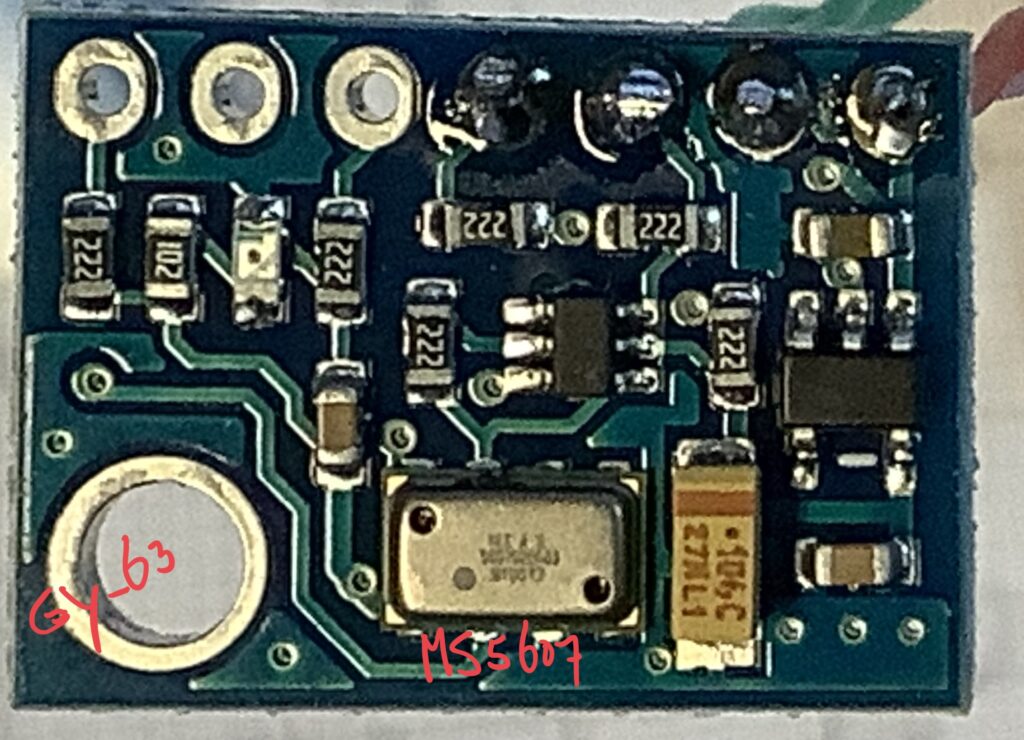
When I finally was able (with 3 magnifying glasses stacked) to read what was on the chip, it said: MS560702BA03. I received MS5607’s that are advertised as MS5611, but obviously they are not!
They are the predecessor of the MS5611, and an obsolete part. And the Big, Really Real Big Problem is, that they have half the resolution. (20 cm). Now, resolution would not necessarily be an issue. Range is the same, all other specs are the same, the code according to the manufacturer is the same.
Looking at many available (Arduino) libraries, you only see the occasional statement that the library is MS56xx compatible, meaning good for both MS5611 and MS5607 (and others).
So, what next? As always I am a sucker for getting to the bottom of the problem, and a $5.00 chip ain’t getting the better of me. But it is annoying to pay for a premium part and get a shitty one. We’ll see what our friends say about it.
My solution for the time being, is to change the code! (What else?)
// code from the manufacturers application note
// https://www.amsys-sensor.com/downloads/notes/MS5XXX-C-code-example-for-MS56xx-MS57xx-MS58xx-AMSYS-an520e.pdf
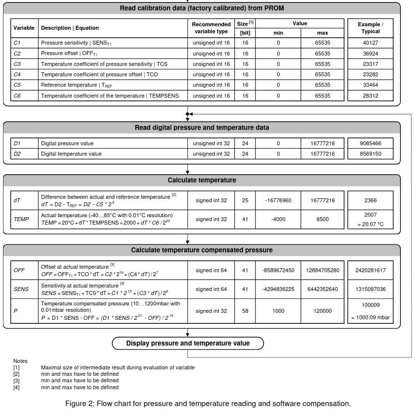
This bit is from the application note.
D2 = cmd-adc (CMD_ADC_D2_CMD_ADC4096); //read D2
D1 = cmd-adc (CMD_ADC_D1_CMD_ADC4096); // read d1
dT=D2-C[5]*pow(2,8); // D2-C[5] * 256
OFF= C[2]*pow(2,17)+dT[4]/pow(2,6);
SENS=C[1]*pow(2,16)+dT*C[3]/pow(2,7);
T=(2000+(dt*C[6])/pow(2,23))/100; P=(((D1*SENS)/pow(2,21)-OFF)/pow(2,15))/100;
The code below is used in the MS5611 library, file MS5611.cpp
*/
{ uint32_t D1 = readRawPressure();
uint32_t D2 = readRawTemperature();
int32_t dT = D2 - (uint32_t)fc[4] * 256;
int64_t OFF = (int64_t)fc[1] * 65536 + (int64_t)fc[3] * dT / 128;
int64_t SENS = (int64_t)fc[0] * 32768 + (int64_t)fc[2] * dT / 256;
if (compensation)
{ int32_t TEMP = 2000 + ((int64_t) dT * fc[5]) / 8388608;
OFF2 = 0;
SENS2 = 0;
if (TEMP < 2000)
{ OFF2 = 5 * ((TEMP - 2000) * (TEMP - 2000)) / 2;
SENS2 = 5 * ((TEMP - 2000) * (TEMP - 2000)) / 4;
}
if (TEMP < -1500)
{ OFF2 = OFF2 + 7 * ((TEMP + 1500) * (TEMP + 1500));
SENS2 = SENS2 + 11 * ((TEMP + 1500) * (TEMP + 1500)) / 2;
}
OFF = OFF - OFF2;
SENS = SENS - SENS2;
}
//uint32_t P = (D1 * SENS / 2097152 - OFF) / 32768; // 507 hPa, readout is exactly half what I expect.
uint32_t P = (D1 * SENS / 2097152 - OFF) / 16384; //
return P;
}
/* Fudging the result for now by dividing the last line by 16k instead of 32k fixes the result, but not the cause.
It’s bad, it’s fixing a hardware problem with a software fudge. But hey, it kept me busy for a few evenings, and that braincell certainly got a tune-up!
My RPM meter for the spindle? working really good. And surprisingly accurate and stable. RPM’s on the Kress 800 are from 10000 to just a shade under 29000. I even printed a box for it, so that the fingers do not get in the way of sharp things. Since usually it is a mess near the spindle, with all kinds of stuff flying around, I decided to keep it as a separate unit. If I need to set a RPM, I can do so easily before cutting. And yeah, I ordered better cutting bits. By the time I have all this finished I could have shaped 100 parts by hand, but there’s no fun in that 😉
Yeah, the spindle problem: turned out the the constant flexing of the mains cable killed the cable. Took 10 years, so I’m not complaining. All is happy again, and the spindle even sounds better. Which probably leads me to another project: Do I upgrade the Router to modern electronics/software or carry on as is? Will it make life easier? Will it make coffee? (Just in case I run out of things to do, one needs to have things lined up!)
update @ 2200: found the differences between the sensors. Testing next..