
Yeah, sort of expected that to happen 😉
With the added mudguard and wheel bearings and other small bits, the Hitec 645MG is struggling to get the gear up. There is a point halfway between up and down, where max force is needed, it’s just how the design of the gear works. In theory I could redesign everything. (Yup, maybe sometime soon). Or I could add another voltage regulator to give it it’s own supply, 6V would work (most of the glider runs on old 5V gear), or solve it for now with slightly more powerful servo.
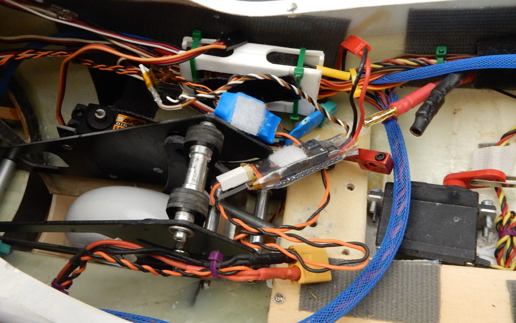
I found a SAVÖX 1256, which has probably twice the torque of the Hitec, so will strap that in for now.
Of course with the way I wired things up, that’s easier said then done. Since I installed a 9 channel Rx in the plane, and needed an extra channel for the Flashy Lights, I came up with the cunning plan to use a single channel for multiple things.
In short, gear up or down is only 2 positions. Light on/off same thing. So why not do a bit of mixing and send the resulting servo signal to an Arduino-Pro-Mini, and let it drive the LG servo and Lights. I cooked that software a year ago, knowing it was a quick fix for a self imposed problem. (That’s what this hobby is all about, if you don’t have a problem, make one!)
Anyway, long story short, the pulse that the servo needs for up or down is hard coded in the software. No biggy, but it means it’s not very convenient when you change servo’s.
Oh, it’s sooo much fun. With the aid of my little magic ToolkitRC.com M6 I measured the output pulses to the servo. 1000-2000mSec. Perfect, but the servo only rotates 90 degrees and a bit? (By the way, there is an software update for the M6, V1.31 dated 23 March 2020)
Oh dear. Now what. Time for a rethink, and do remember in future that you really want a 180 degree servo!
After some reflection and relaxing in the sun, I remembered that I used to convert servo’s to 180 degrees by adding a few resistors to the feedback pot. That triggered of course the thought ”did I maybe modify that servo?”.
And the answer is yes, I did! Funny enough I posted that same fact on 3rd Dec 2016 on my Facebook account. Oh where would I be without my facebook memory. Scary..
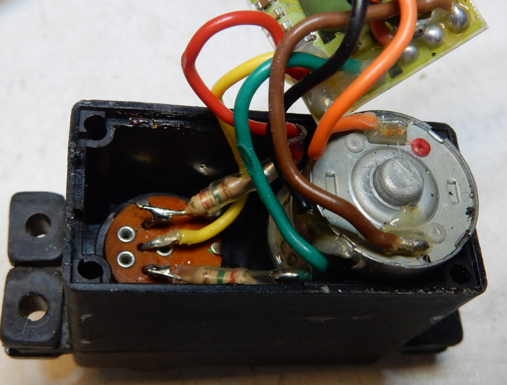
Well that sure was a fun exercise for a locked-down Saturday. So next question is: Am I going to modify the Savox? The answer is below. Same trick, 2 * 1.5kOhm resisters either side of the potentiometer will do the trick. Funny this servo is rated to produce 4096 steps. It never stops to amaze me how you can get that resolution from a cheap 5k pot. But they work, so I’m not counting! by the way, there are no wires in this servo, which should make it more reliable (cheaper). But it does mean some sort of skill is required to remove the pcb!

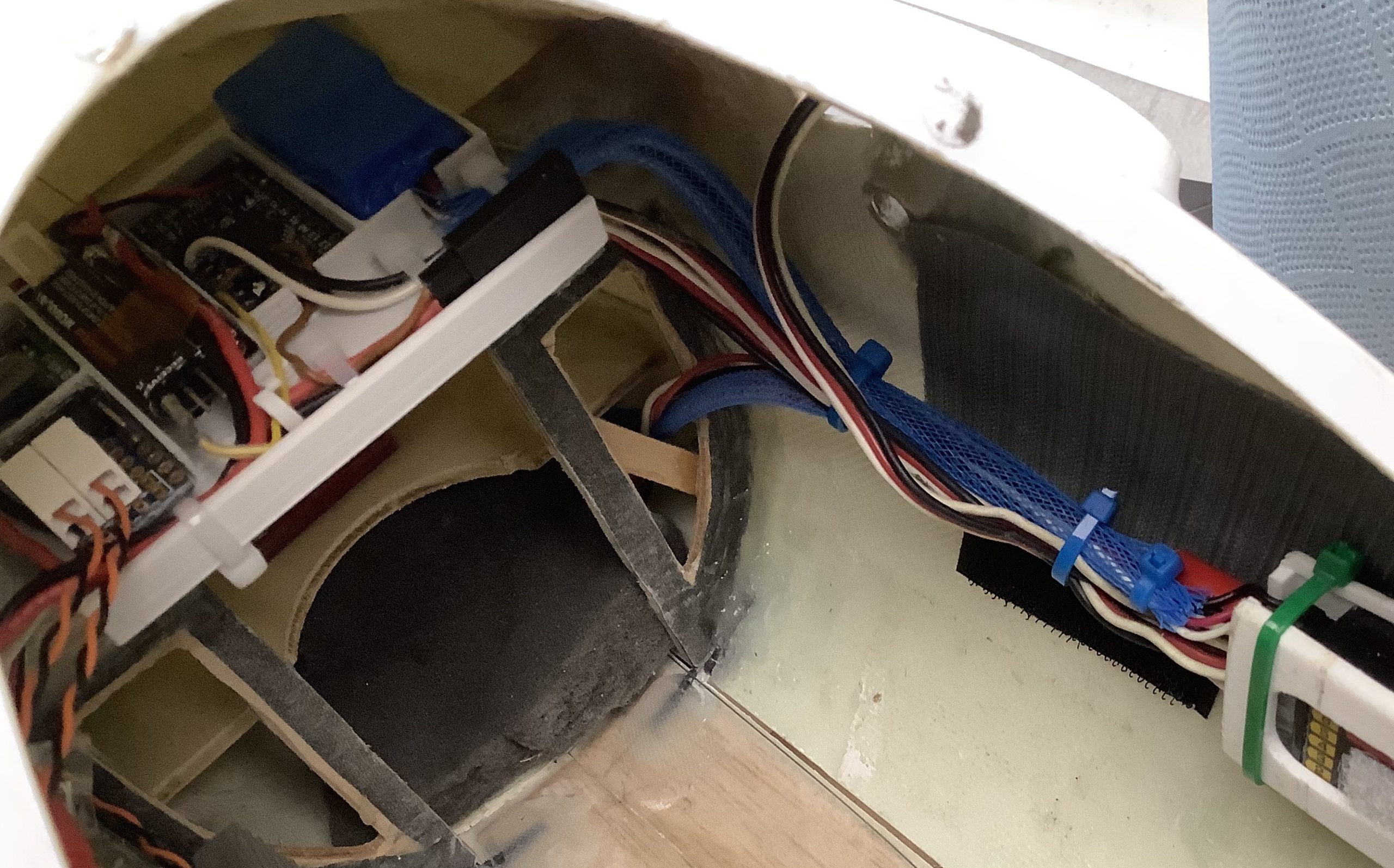
And while at it, might as well try to sort out the wiring mess a bit. I’ve got some space at the top of the fuselage, out of sight.


By the way, that stepdown converter acts as a current limiter as well. Max current the chip will produce is 4 Amps, stall current for the servo is 5 A. Should be safe. And since it is only ever used for up and down, it is not likely to get warm. And if it does, it will disconnect, saving the battery. In theory this is what is supposed to happen. Real life might work differently.
So, that’s enough for Corona-Easter-2020. Left’s hope and pray the world will not have to repeat this ever again!