The first cut is the hardest

 CNC  Comments Off on The first cut is the hardest
Jul 252020
 

What took you so long? No idea.. More then 10 years ago I got myself a CNC-router with the idea that I would be able to metal metal parts. I’ve used it up to now mostly for non-metal parts. But retirement has given me enough time to finally sort things out. That and a better understanding of materials, cutting speeds etc. And after the smokies I had here, this is much better!

So, here we are: first part. This is a bit of steel which should probably not have that name. It cuts like butter, which is good for my confidence!

first part that was not produced with smoke and fire!
need to make a better jig, but the idea works.
and the final part.

The observing reader will notice that my hole sizes are off. Original is 6 mm bolts, scaled would be 2 mm. I feel that’s a bit thin. I’ll use standard 3mm ones , marked 8.8= 800 Newton/mm2.

  • M2, core area is 1.8 mm2. 1.8 * 80 =144 Kgf.
  • M2.5, core area is 3 mm2. 3.0 * 80 = 240 Kgf
  • M3, core area 4.5 mm2. 4.5 * 80 = 360 Kgf.

(not sure I have the right table here, check later! Values feel about right though) See here and this one

Ok, I’ll drill them 2.0 for now, looks like that is really enough. I’ll leave the one going through the spar at 3 mm, makes life easier. Yeah, I know, you should sort this out BEFORE cutting metal. Me thinks I’m due for a coffee break!

Trying with 0.6 mm stainless steel. It’s shiny, no other identification. Problem 1: it does not stay down on the board very well, so I really need a DOWN cut bit. (learned that in a hurry!) Not to be stopped that easy, I went slow, lots of cooling fluid, and managed these 2 parts. Progress is being made by counting the bits that did not work. Also, because the sheet is not fixed properly, I get some chatter, visible on the edges and general outline. All to be expected and just needs time to fix. I think it would also be better to have the cooling nozzle fixed to the head, moving around by hand as we go is possible, but not great.

clamp between 2 bars..
it works!

what a mess…..

tip-work

 Acroduster  Comments Off on tip-work
Jun 282020
 
Lower wing as it should be..

After glueing the trailing edge wood (not shaped to final yet!) it was time to do a bit of tube-bending. It’s 4 mm tube, and for the life of me, I don’t know why it is so soft. Almost feels like copper tubing. Never mind, just try to match the shape.

bend wood and bend tube

Trying to hold the camera at just the right distance and level is probably easy if you were to create a support. Maybe one day? I just needed to get the tip shape lined up with the trailing edge, and make sure the lines ‘flow’.

A quick copy paste on the original drawing makes it look close enough. There is some distortion in the camera, the rib distances are correct.

Good enough to carry on!

it matches well enough.

In the meantime I’m making more ribs, more trailing edges, more of everything. But that has all been documented, I’m not repeating it 😉

Nice weather

 Acroduster  Comments Off on Nice weather
Sep 192019
 

There is no reason for the pics, it’s just nice weather and it looks great 😉 Weight as you see it here is 1850 grams.

Of course I took it to our end of season do, just to show off.

if you look careful, you’ll spot the rudder. The Bucker belongs to Ed, who took this picture of these two armchair pilots..

bare side
side with stringers and fake covering.
under carriage with the printed streamline fairings.

 Posted by at 12:40 pm  Tagged with:

After brazing

 Acroduster  Comments Off on After brazing
Aug 212019
 

Closeups of my handywork. After sandblasting I ‘ll reheat the joints to make them flow a bit more and fill any voids leftover. This will be for cosmetical reasons only.

front u/c support
rear u/c support – front wing support

bottom parts 2mm steel, top 3 mm steel.

Looking good!

Adding some direction

 Acroduster  Comments Off on Adding some direction
Aug 142019
 

Just a relative quick job tonight: making the fin. The only noteworthy item would be that after installing the ribs, I still had to drill a hole for the bracing rods. I decided to simply cut a slit with the Dremel and enlarge it to fit the tube. Seems to work well, and since it will be hidden, it’s good enough for now. Consider this a practice run for the elevators.

rudder ribs
..start of fin construction.

 Posted by at 5:34 pm  Tagged with:

Designing and building the motor mount.

 Acroduster  Comments Off on Designing and building the motor mount.
Aug 032019
 

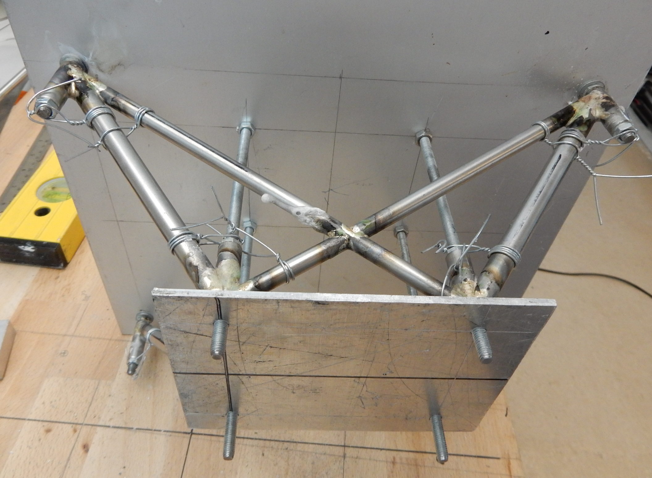
Once it is all finished it looks easy. At the start it’s more like ‘how am I going to tackle this? I decided to use a 3 mm alu plate as a mount for the short tubes that hold everything together. This way I could mount some 5 mm wire studs to hold the motor, and line things up as I think they should be. The frame bolts are actually mounted in the frame, which makes everything line up perfectly. Mind you, this is probably version 1, when I get further along I might need to change things because of balancing, place for the exhaust, servo’s etc. The mounting tubes are still oversized, but better a bit longer then too short. The top cross bracing went OK, when I started adding the bottom ones, I found there is no space for them because of the Walbro carb. In theory the supports on 3 sides would be enough. I also have to think of a place for the exhaust, might have to make something special, since I really don’t want the hot exhaust next to the carb.

I ran out of tubes, so next stop is to figure out what I need, place the order and wait.

The mount weighs nothing of course, I did not weigh it, but I would guess around 90 grams.

For the clever ones: no sidetrust in the mount? Based on good advice I decide to use a throttle to rudder mix to keep things lined up. I can always change it! I also might use this mount for running in. (There is no need for it, I know, but I want to see how it holds mechanically before letting go into the big blue yonder.!)

plates to mount the tubing for brazing.
..bottom view
side view
Top view, those bushings for the bolts will be shortened and I will add an inside tube to prevent buckling. All in good time!

And we have a Valach

 Acroduster  Comments Off on And we have a Valach
Jul 242019
 
test fitting the bit at the front.

It fits, no worries there! It’s gonna be jus’ perfect! I am sure I can’t resist building the engine mount next. It might not be the correct size, because depending on the CG I will move the engine forward/back. But it will be a good exercise, and it makes things look real..

Center of Gravity

 Acroduster  Comments Off on Center of Gravity
Jul 232019
 

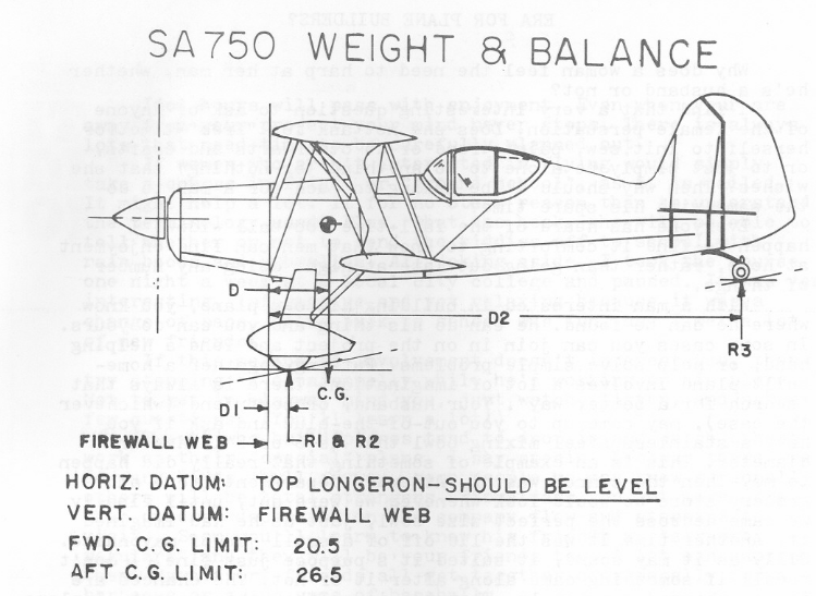
It’s never too early to add that famous mark. Of course this is the full size one, and I might not like it, but it is a good enough place to start!

23.5″ avg, scaled down locates the CG at 200 mm. TLAR as they say.
And of course some heavy metal to balance everything 😉

Probably overpowers the plane, but it has the right sound, and I have seen the engine long enough in use to know it is going to be a happy marriage! Hey, this thing is called an Acroduster, the more oomph, the better!

Sandblasting

 Acroduster  Comments Off on Sandblasting
Jul 232019
 

Last year I had some fine nice sand left over from doing some garden-diy-ing. ‘Just in case’ I stored it in a nice dry place, knowing that one day, dry sand would come in handy.

I knew from the onset that I needed to find a way to clean up my brazed parts. Up to now I used the 3M-scotchbrite pads and lots of elbow grease. However, you never get into the nooks and crannies. I already had a friend offer his help, but of course there is always the thought ”I could do this myself”. Lots of googling and you know sandblasting can be dangerous for your health, so please only do this if you are a responsible adult, and know how to take the proper precautions!

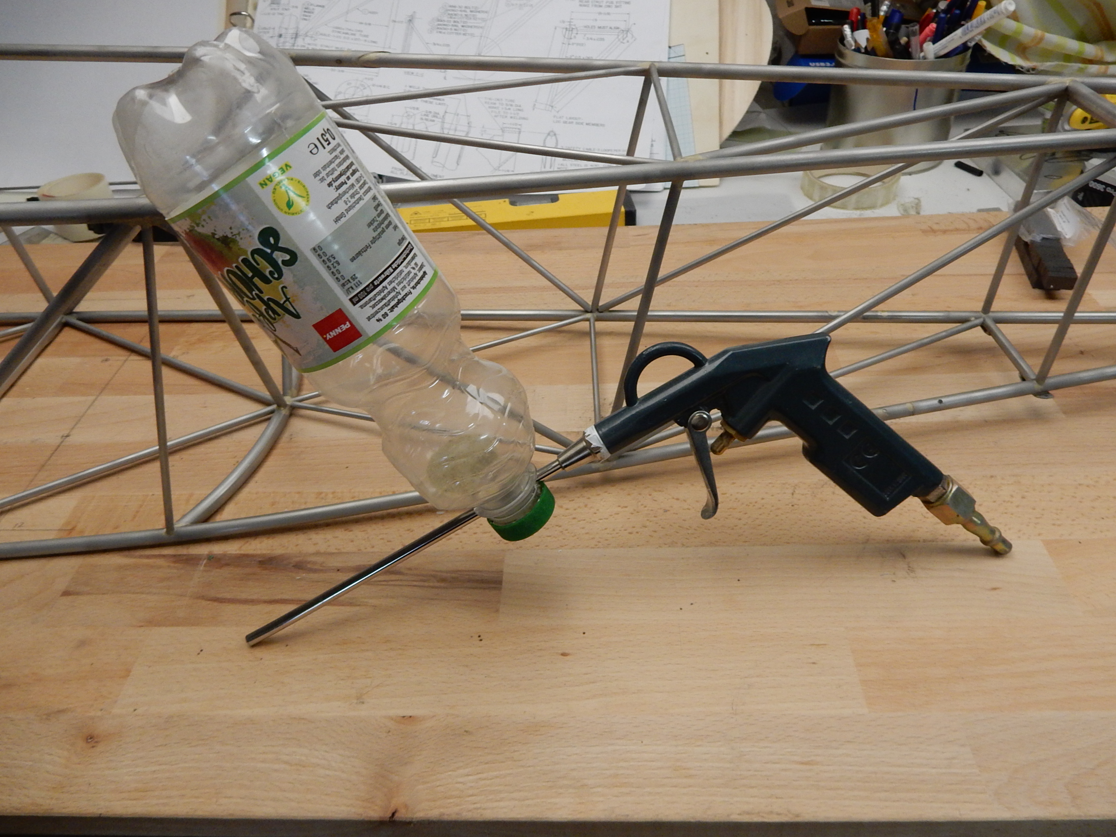
The mechanics do not appear to be complicated, as shown by the many DIY sandblasting contraptions on utoob. After playing around with some fittings and getting lots of sand in the wrong places, I thought I’d try the most basic version: the plastic bottle version.

So, I got an empty bottle, drilled 2 holes in the neck, modified an airpistol, filled up the bottle with some dry sand, squeezed the trigger, and wow, this works!!

The only downside and need for further work is that my compressor does not really have enough oomph to supply a lot of air. So I blast 10 secs, wait 20 sec etc. I might try with a smaller tube, less air, less sand but more continuous blasting. I did not build an enclosure, I just use the ferns at the edge of the garden as my shield, and they do a good job at catching all the sand!

Yes, I know, the surface is not evenly blasted, there are shiny parts etc. However, the main thing I wanted to achieve was to get rid of all the gunge, and that worked 100%. I still need to add a gazillion bits of tubing and supports, so there will be more opportunities to hit every part. For now, I am happy with the result!

Oh, by the way, so far the fuse weighs in at 973 gram, which is pretty good going. I only used 30 grams silver to solder everything so far.

Tubes everywhere..

 Acroduster  Comments Off on Tubes everywhere..
Jul 222019
 

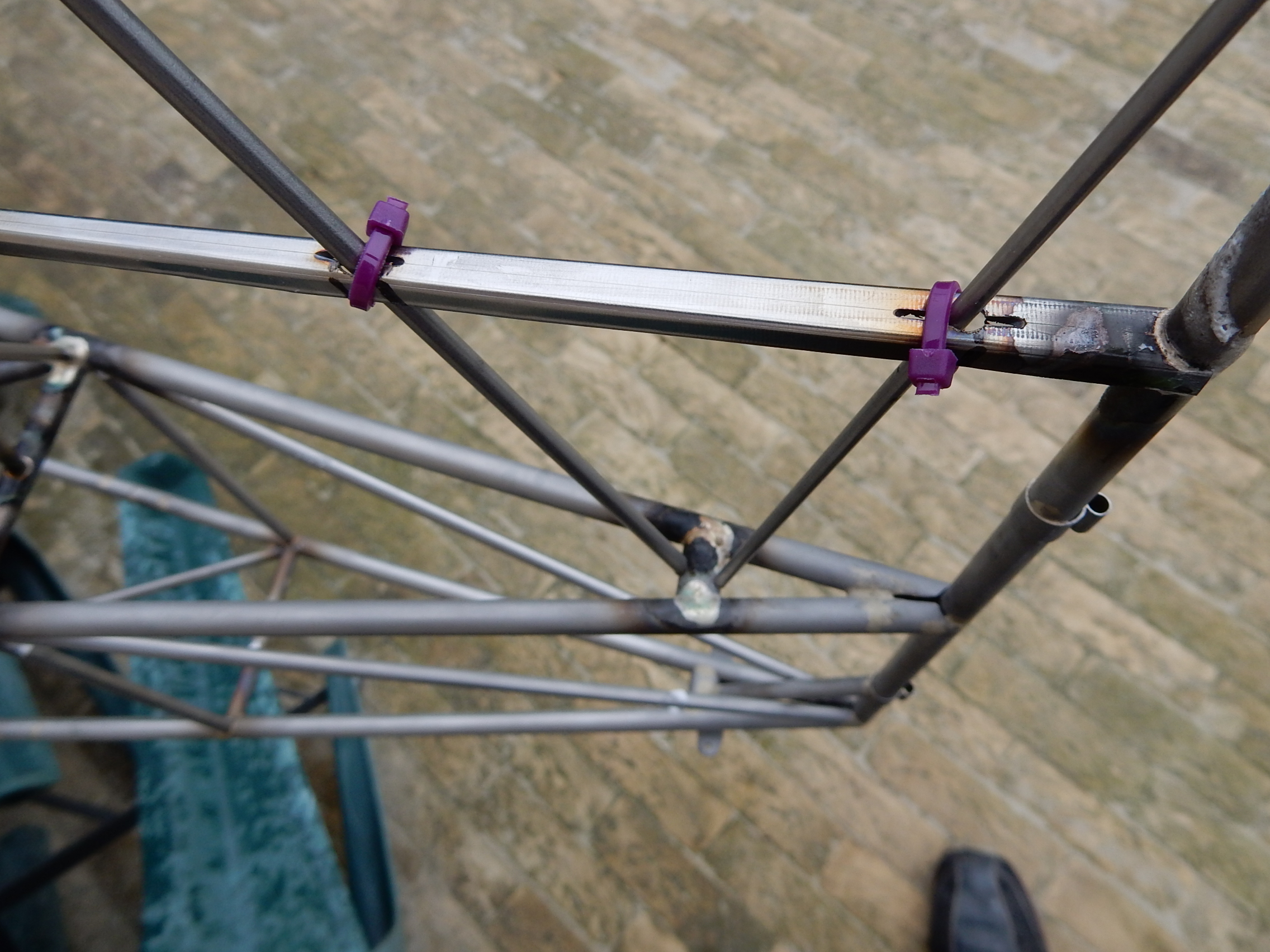
After a few weeks of putting bits of tubing together, I am at the point where things start to look like something you would recognize as a fuselage.

This morning I cleaned up the fuse with a diy sandblaster, much to my surprise this went really well. It’s the usual bucket of dry sand, empty bottle and some compressed air contraption. Needless to say, do wear a decent respirator. For the rest, the neighbors are building an extension to their house, I blame all the extra sand in the air on that!

The brazing is getting easier as we go along, however, the further the construction progresses, the more time it takes to make the parts. (When it looks 80 complete, you have 80% of the work ahead of you 😉

Anyways, below some pics from the various stages of construction. I was at this point still struggling getting the right flame from my torch. After suffering from empty bottles, I have now switched to a decent propane tank (still using the oxy-bottles) and a .6 or .7 mm needle as a welding tip. When I am all finished I will be an expert and write a nice story about the pitfalls of silver soldering.

Alu foil works great for protection of the ply when soldering. 4 layers works fine.
..next time I’ll do it different.
it almost looks real!
these are the templates for rudder/stab/elevator.
as it says: rudder horn.