I’m going to make one post a week, and add all the stuff I do in this post. Unless I change me mind.
I wondered how long I have been working on this: looks like first metal was cut in June 2019. Not bad.
Before going too far I thought it would be a good idea to see if the wing still fits. Since it is a nice pleasant day, it was a good moment for a selfie.
using this image to see if things are square.
There is some work left on the aileron, once that is done, I’ll do the root rib. Somewhere in between I also have to build the servo/linkage/bellcrank.
Sounds like another fun week coming up!
challenging to get the shape rightthis is not the same type of plane, but of similar origin/construction
Some of the drawings are not to scale, which is no problem if you build the full size version. A few important ribs are drawn full size, and from there it is easy to find the missing dimensions. Because the dimensions on a piece of paper are very hard to determine accurately, I found I needed to start measuring from the full size ribs on paper. From there it is easier to scale everything back to 1/3 scale.
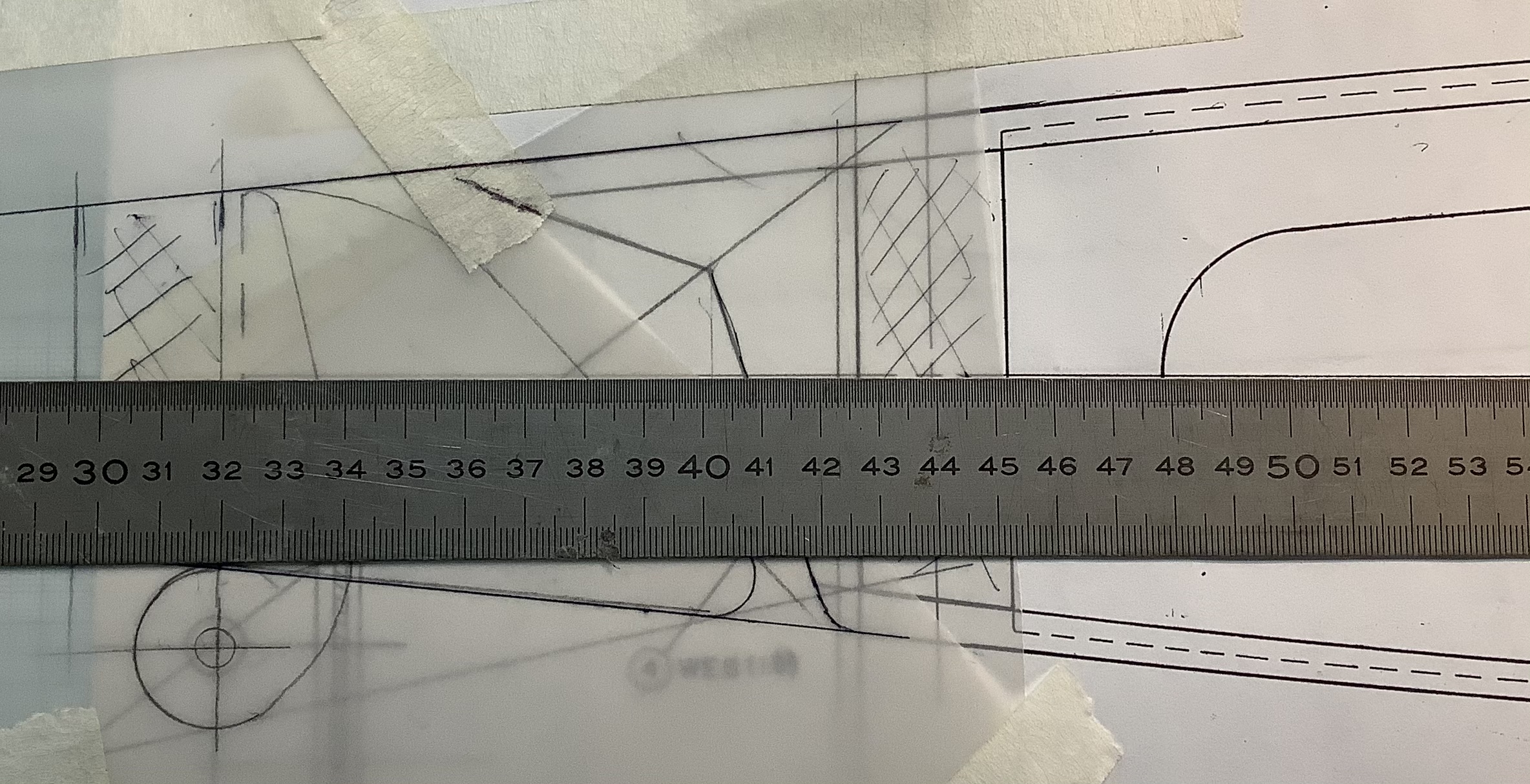
There is a drawing with dimension to create the curved trailing edge, but there was no reference to the distances to the spars. Anyway, doing the extra work was not difficult, just time consuming.
dimensions for full sizewing goes downthis also gives the max deflection of the aileron.
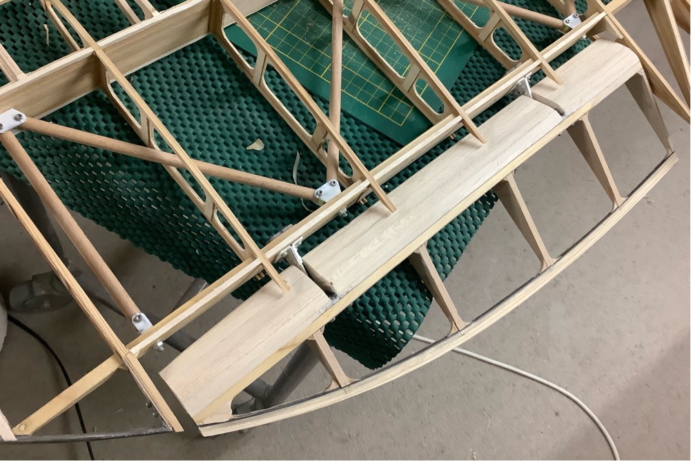
Still trying to work out the trailing edge. It’s a 1″ alu shaped piece. Since it is not available any more, people use a traditional wooden one. However, since the ribs are quite small at that point I’m still not sure how to attach it. One option is the method using gussets on top and bottom.
trailing edge with some carbon for support.
Build support for the trailing edge and aileron spar. This should keep things lined up. Next step, attaching the root ribs to the trailing edge and build the aileron ribs.
While I have the router setup for cutting wood, I’ll do the nose templates for the ASK21 wing.
lots of filling and sanding to get to this shape!
Lots of fiddly bits, progress seems slow, but it’s raining, so who cares. Getting the aileron spar dimension correct is what is holding me up.
I am going to cut some negative ribs to slide over the aileron ribs, so that the trailing edge ends up where I want it. Even with the jigs on the building board I am not getting the right alignment results. Which probably means there is an error somewhere.
Sometimes you miss the obvious: there are no capstrips on the aileron ribs! that makes things easier. Tomorrow is another day, another challenge.
oh dear, is that not dangerous? nah, get’s the job done. (4x4mm with 2 mm slot)and some fun with the wingtips
one day I’ll turn this into a readable story, now it’s my diary!
The ailerons contain quite a lot of parts. Apart from hinges, there is also a link to drive the top wing aileron. And the link to the bell-crank that is connected to the control stick.
now add some brass bearing bushingsa bit of riveting and we’re done
I started using a 1.5mm bit for cutting, it allows a higher spindle rpm, and better cutting of holes. Using the 2 mm bit to drill the holes was not really a good idea. Milling cutters are not drills! Also had to reduce the cutting depth per pass to max 0.3mm. A cnc router designed for wood does not have the stiffness do do any more. (At least mine does not) So with these settings and mild steel, things go great. The material for these parts is stuff from the local DIY shop, supposedly 1 mm thick. It’s more like 0.9, but I’m not complaining.
Drawings show full size part.
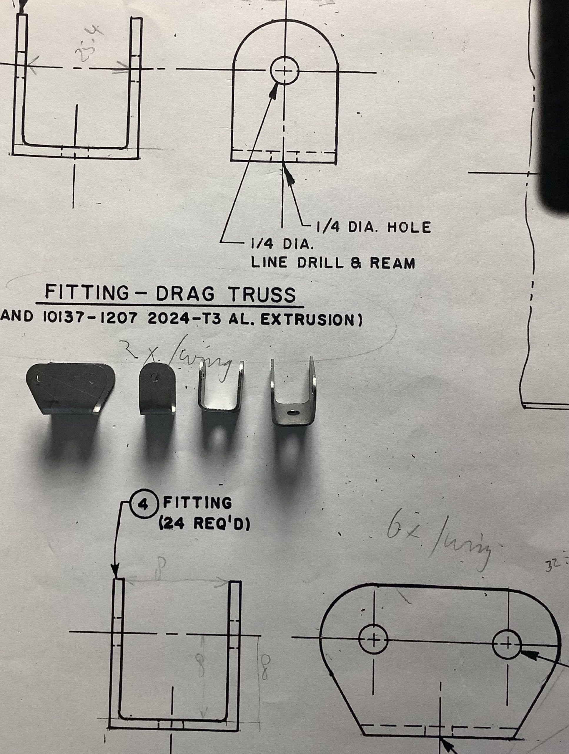
Anyways, just for reference: The original material is listed in ‘Standard Aerospace Extruded Shapes’, these ones start life as ‘AND10136-2403’ (AND stands for Army-Navy-Drawings.) It’s an aluminium T-profile to you and me. Finding out how it is supposed to be made makes it easier to make something that ‘will be close enough’.
bearing holes are drilled 2 mm, might go to 2.5 in the final assembly.
The result after paying close attention to alignment and clamping. This will do. Make a few more and on to the next step!
The reason I have 2 pcs joined is that I use 2 mm drill bits stuck through the outermost holes to align the blanks before bending. This ensures (hopefully) that that both end up equal.
The truss tubes provide the for/aft strength of the wing. Since these are in place now, I continue with the ailerons horns and linkages. Once those are done, I can start on the aileron and trailing edge. Then only repeat 3 more times. Funny how some of the ribs look skewed, but it’s honestly the camera, real life is perfect. And that second nose rib from the left, even that is where it is supposed to be!
plans show full size, mine are mysize. 2024-T3 is what we used to call dural. using cheap dowel for now. 0.85 euro dowels or 8 euro tubes.. I’ll think about it.
Making the aileron attachment points is next. Real life and drawing do not always match, but it’s close. (The base of the horn is approx 1 mm too high. Of course I should have measured that beforehand.) There will be a brass bushing in the big hole, and I will have a look if I can find 2 mm rivets. If not, the 2 mm bolts will do. Might put a bit of solder on the back, so that even when the rivets do nothing, it will still be stronger than needed. And I need to work out a clamp to allow accurate bending of that flange.
Aileron hinge: first trial part, forgot one ‘cut on the outside of the contour’ section. For the rest acceptable.
Finally getting the hang of producing chips in a consistent way. I think I need approx 36 pcs of the brackets you see in the second image. By the time I have those made, I’ll be an experd.
These by the way are fittings for truss-tubes in the wings. Once the wings are covered nobody will ever see them again.
Below is an image from the build process of a full-size version. The red tubes are 1″ diameter, the bolts at the bottom of the image are 1/4″ (6 mm)
All that stuff is not that big!
Brackets can be seen where red tubes connect. My version of the brackets.
I wanted to use this nifty little display for my RPM display of the spindle on the CNC-Router. It somehow switched to a 128*32 mode.
Digging in the code, I found a problem (for me, in this sketch) Activating the 128*64 define in Adafruit_SSD1306.h library, fixed it.
Yes, of course, it (they) will go into the plane as well, that’s why I got them 😉
/*!
* @file Adafruit_SSD1306.h
* This is part of for Adafruit's SSD1306 library for monochrome
* OLED displays: http://www.adafruit.com/category/63_98
* Written by Limor Fried/Ladyada for Adafruit Industries,
*/
#ifndef _Adafruit_SSD1306_H_
#define _Adafruit_SSD1306_H_
// Note: my display only showed 32 lines,
// changing this define to the one below
// cured the problem. Standard 'define SSD1306_128_32' is wrong.
// Kees Blokland, 2 July 2020
// ONE of the following three lines must be #defined:
#define SSD1306_128_64
//#define SSD1306_128_32
Update: The better and proper way is to add the directives from the updated library in the source code:
Adafruit_SSD1306 display(128, 64, &Wire, 4); // This forces 128*64 display and a reset. Before it was:
Adafruit_SSD1306 display(4);
So the display is working, but values are jumping around too much. This is a known arduino limitation, and somewhere I have a library from ElectricRCAircraftGuy that solves the problem to a large extend.
Oh, and in the meantime the router motor has decided to stop. It did sound funny lately, more work! Usual case of ‘last night it worked, today it does not’. Using a Dremel for creating revolutions to count.
Yes the shed roof is still being worked on too, and so is the garden, and a myriad of urgent stuff…
After glueing the trailing edge wood (not shaped to final yet!) it was time to do a bit of tube-bending. It’s 4 mm tube, and for the life of me, I don’t know why it is so soft. Almost feels like copper tubing. Never mind, just try to match the shape.
bend wood and bend tube
Trying to hold the camera at just the right distance and level is probably easy if you were to create a support. Maybe one day? I just needed to get the tip shape lined up with the trailing edge, and make sure the lines ‘flow’.
A quick copy paste on the original drawing makes it look close enough. There is some distortion in the camera, the rib distances are correct.
Good enough to carry on!
it matches well enough.
In the meantime I’m making more ribs, more trailing edges, more of everything. But that has all been documented, I’m not repeating it 😉
The ribs trimmed to size (sort of) Even at this stage the wing is very stiff. Normally in a balsa/built up wing, it is pretty easy to twist the structure. Due to the way the ribs are built, there is an decent amount of torsional stiffness, even at this stage. Next I have to make the root rib and tips ribs.
Next maybe the aileron, since that takes quite a bit of additional mechanical work. The TE can be added as the last bit. so that there is a nice curve along the ribs.
I’m still thinking about the tubular bracing in the wings. I don’t really need it. If I change my mind I can add it at the end. I will save quite a bit of weight, is there just ”because the original has it”. The leading edge covering will provide enough for-aft stiffness.
For my own reference: ribs are slightly under 10 grams before trimming to length. The whole wing at this stage is 335 gram, that’s including some metal. What the target weight is? No idea to be honest, I would think around 700-800 gram all ready. But up to a kilo for each wing will be ok, I need the weight!
AcrodusterComments Off on it’s getting serious now..
Jun162020
around 40 ribs cut, and 10 glued uplooking ribly..
A good day was had, is the saying. Over the last week or so I have been bending the cap-strips. It is a time consuming job. First you soak them for a few days, then clamp them in a jig, then let dry for at least 24 hours. Repeat.
Since there are always minor variations in the construction, my plan is to route the outline to final shape once I have enough ribs done. That would make them all exactly the same, which is the whole purpose of all this effort.