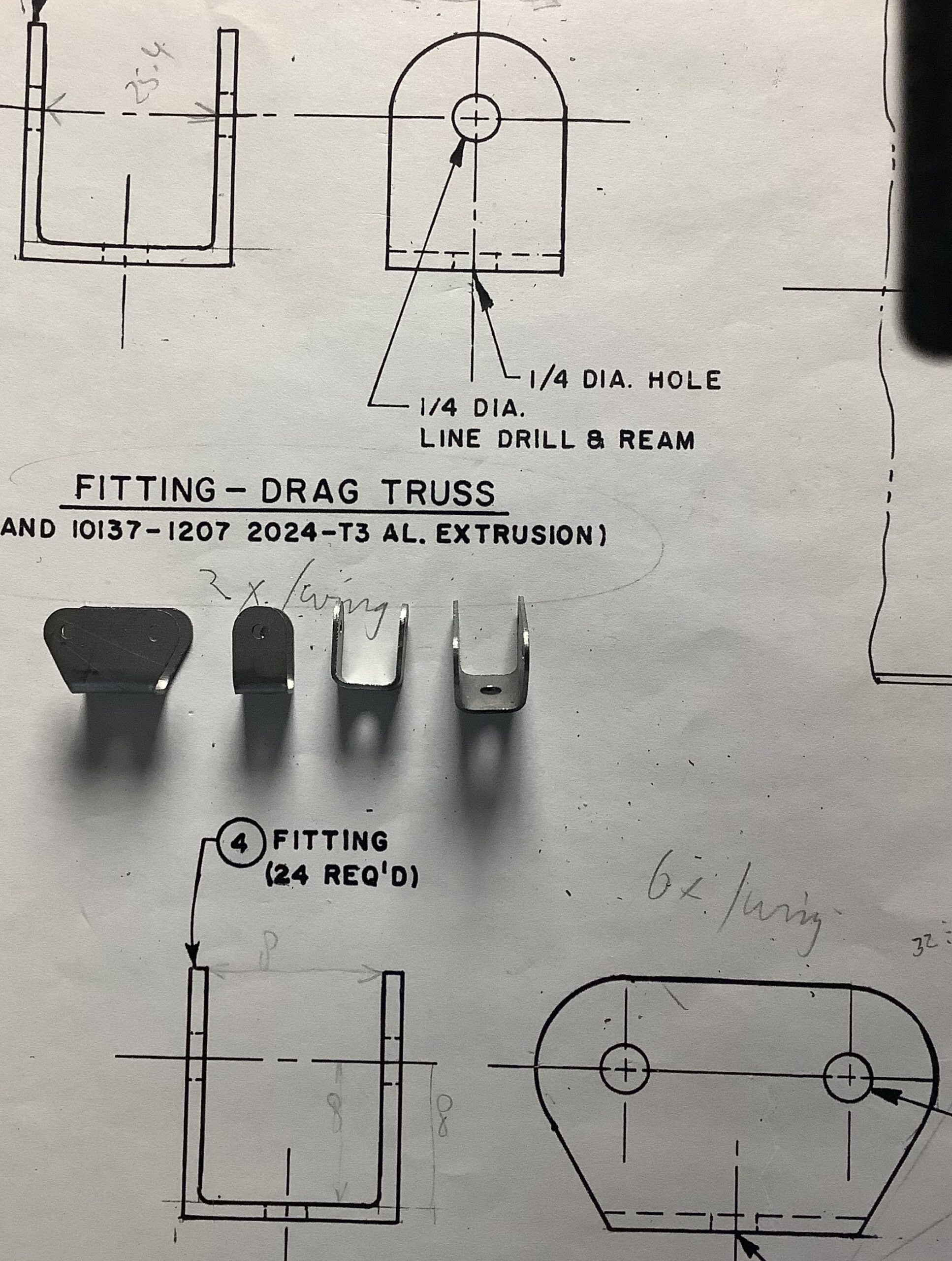
The truss tubes provide the for/aft strength of the wing. Since these are in place now, I continue with the ailerons horns and linkages. Once those are done, I can start on the aileron and trailing edge. Then only repeat 3 more times. Funny how some of the ribs look skewed, but it’s honestly the camera, real life is perfect. And that second nose rib from the left, even that is where it is supposed to be!
plans show full size, mine are mysize. 2024-T3 is what we used to call dural. using cheap dowel for now. 0.85 euro dowels or 8 euro tubes.. I’ll think about it.
Making the aileron attachment points is next. Real life and drawing do not always match, but it’s close. (The base of the horn is approx 1 mm too high. Of course I should have measured that beforehand.) There will be a brass bushing in the big hole, and I will have a look if I can find 2 mm rivets. If not, the 2 mm bolts will do. Might put a bit of solder on the back, so that even when the rivets do nothing, it will still be stronger than needed. And I need to work out a clamp to allow accurate bending of that flange.
Aileron hinge: first trial part, forgot one ‘cut on the outside of the contour’ section. For the rest acceptable.
Finally getting the hang of producing chips in a consistent way. I think I need approx 36 pcs of the brackets you see in the second image. By the time I have those made, I’ll be an experd.
These by the way are fittings for truss-tubes in the wings. Once the wings are covered nobody will ever see them again.
Below is an image from the build process of a full-size version. The red tubes are 1″ diameter, the bolts at the bottom of the image are 1/4″ (6 mm)
All that stuff is not that big!
Brackets can be seen where red tubes connect. My version of the brackets.
What took you so long? No idea.. More then 10 years ago I got myself a CNC-router with the idea that I would be able to metal metal parts. I’ve used it up to now mostly for non-metal parts. But retirement has given me enough time to finally sort things out. That and a better understanding of materials, cutting speeds etc. And after the smokies I had here, this is much better!
So, here we are: first part. This is a bit of steel which should probably not have that name. It cuts like butter, which is good for my confidence!
first part that was not produced with smoke and fire!need to make a better jig, but the idea works. and the final part.
The observing reader will notice that my hole sizes are off. Original is 6 mm bolts, scaled would be 2 mm. I feel that’s a bit thin. I’ll use standard 3mm ones , marked 8.8= 800 Newton/mm2.
M2, core area is 1.8 mm2. 1.8 * 80 =144 Kgf.
M2.5, core area is 3 mm2. 3.0 * 80 = 240 Kgf
M3, core area 4.5 mm2. 4.5 * 80 = 360 Kgf.
(not sure I have the right table here, check later! Values feel about right though) See here and this one
Ok, I’ll drill them 2.0 for now, looks like that is really enough. I’ll leave the one going through the spar at 3 mm, makes life easier. Yeah, I know, you should sort this out BEFORE cutting metal. Me thinks I’m due for a coffee break!
Trying with 0.6 mm stainless steel. It’s shiny, no other identification. Problem 1: it does not stay down on the board very well, so I really need a DOWN cut bit. (learned that in a hurry!) Not to be stopped that easy, I went slow, lots of cooling fluid, and managed these 2 parts. Progress is being made by counting the bits that did not work. Also, because the sheet is not fixed properly, I get some chatter, visible on the edges and general outline. All to be expected and just needs time to fix. I think it would also be better to have the cooling nozzle fixed to the head, moving around by hand as we go is possible, but not great.
Finally got the airspeed sensors, so what better to do on a rainy afternoon them to play with them? First the specs: Datasheet, and a picture. Bear in mind that all these diy chips are basically old stuff. This one dates from 2012. Obviously nothing wrong with them, they are still used in a lot of equipment, but they are not the smallest of parts! However, this makes it so easy for us diy-ers to play with them.
which tube goes where.
The metal probe weighs approx 10 gram, with electronics, housing etc, ca 40 gram. (too much cabling, and unwanted plastic). I don’t want to stick that on the tail of a glider yet. I’ll use that on the wingtip of the Carden. ( I think, maybe, or something). Easiest for testing is to connect the sensor to the input of my JetiBox. (I think this can be done) and stick it on the car. We’ll see where this goes.
Some how the Jetibox only displays 14 sensors, (supposed to be 16) and most of them are for the GPS that is not present and disabled. I guess I have to ‘fix’ the software for this. Can’t think of another way at the moment.
The sensors-information must be stored along with the Rx identity in the JetiBox. (Not in the transmitter, in the JetiboxProfi box thingy.) Good project for another rainy-day, because I suggested to one of our BigGlider guys that I could use this to monitor ‘from the side’ if and when he has signal dropouts. I can do it at the moment, but I would still like to see the airspeed at the same time. That was the idea behind the stand-alone system. Stick it on anything, and monitor from Jetibox. Actually, with all the sensors on board you could monitor lots of things, without having to interfere with the electronics of the plane. (Fokker-E3 rings a bell, what speed is it really moving, and would it not be nice for it to complain when things are getting dicey. Just a thought…)
sort of prototype, just enough to keep things in place
Wingtip? If I add a small 2s 150mAh lipo it will be a completely self contained, stand-alone unit, that is connected to the DS-14. Weight is easily added to the opposite tip to balance things. That, or stick it an the rudder, the Carden won’t mind so much. Much fun to be had!!
And in the meantime, our friends delivered a bunch of cutters for the CNC-machine and some parts for making a mist-cooling system. As always, the general idea is present, the execution is still to be puzzled out. Where do I put stuff?? On the router head so it moves along with stuff I cut, (wishful thinking) , or nail it to the bottom and for the few small parts I have to make it is ok to simply spray enough the centre of the part. And I need some cutting fluid. Look for local cutting fluid, and start doing it!
I wanted to use this nifty little display for my RPM display of the spindle on the CNC-Router. It somehow switched to a 128*32 mode.
Digging in the code, I found a problem (for me, in this sketch) Activating the 128*64 define in Adafruit_SSD1306.h library, fixed it.
Yes, of course, it (they) will go into the plane as well, that’s why I got them 😉
/*!
* @file Adafruit_SSD1306.h
* This is part of for Adafruit's SSD1306 library for monochrome
* OLED displays: http://www.adafruit.com/category/63_98
* Written by Limor Fried/Ladyada for Adafruit Industries,
*/
#ifndef _Adafruit_SSD1306_H_
#define _Adafruit_SSD1306_H_
// Note: my display only showed 32 lines,
// changing this define to the one below
// cured the problem. Standard 'define SSD1306_128_32' is wrong.
// Kees Blokland, 2 July 2020
// ONE of the following three lines must be #defined:
#define SSD1306_128_64
//#define SSD1306_128_32
Update: The better and proper way is to add the directives from the updated library in the source code:
Adafruit_SSD1306 display(128, 64, &Wire, 4); // This forces 128*64 display and a reset. Before it was:
Adafruit_SSD1306 display(4);
So the display is working, but values are jumping around too much. This is a known arduino limitation, and somewhere I have a library from ElectricRCAircraftGuy that solves the problem to a large extend.
Oh, and in the meantime the router motor has decided to stop. It did sound funny lately, more work! Usual case of ‘last night it worked, today it does not’. Using a Dremel for creating revolutions to count.
Yes the shed roof is still being worked on too, and so is the garden, and a myriad of urgent stuff…
For the first time in months it’s raining today! Just checked my rain tanks, they are filling slooow, the plumbing is ok, no leaks. (Trust me to install rainwater capture tanks, and then it does not rain for months!)
Challenge of the day: I really, really want to make these small metal parts myself. Problem I have is not Knowing Enough about milling speeds. (Not knowing anything about cutting metal is probably closer to the truth).
Truss drag fitting: result in 0.5 mm mild steel.
So when I tried to cut some stainless steel I get a red hot milling bit, with sparks flying everywhere. That, my friend, is NOT GOOD. I already went down to the lowest speed my spindle runs (10k), slowest feed (30mm/min) lowest plunge depth (0.5mm). I have a 2 mm 3 flute bit in my Kress 800.
What now? I know about cnccookbook.com, but the GWizard software only runs on a Windowz system. ;-(
Anyway, installed a trial version of GWizard on the work-laptop (which I will not use for work anyway) and plugged in the numbers I used. Well, lets say it recommended I do not try this at home!
What should I do next? Get better and more suitable mills is the obvious answer! Stuff that works for plywood, does not make a good metal cutter. But first let’s see what I have. I have a bunch of short 1 mm cutters. Long story short, I need a higher feed-rate and lower RPM. Easy said. Now try to make that router behave. Since it’s raining, some good Irish country music playing in the back, lets tackle it!
After some googlings I think I found bits similar to what I have. The company that mine came from 10 years ago, does not have a search function on their website. Going through loads of pdf books is a bit too much fun today.
mine are not AlTiN coated, I should use lower speeds I guess.
First we needs something to actually measure spindle RPM. I am sure I have an prop-rpm gadget somewhere. But ‘Somewhere‘ is a bit elusive at present, I’ll try to remember where I put it. Can’t find it….
with all the happy numbers plugged in.
Playing around a bit more, I can actually use the 2 mm HSS mill that I have mounted now, needs 60 mm/min @ 5300 RPM, cutting depth is 0.5mm, slot width =2 mm
I did find some of my old reflective sensors, so we are almost done. (famous last words). Fire up the soldering iron, and cook up some code.