more rib testing

 Acroduster  Comments Off on more rib testing
Jun 062020
 

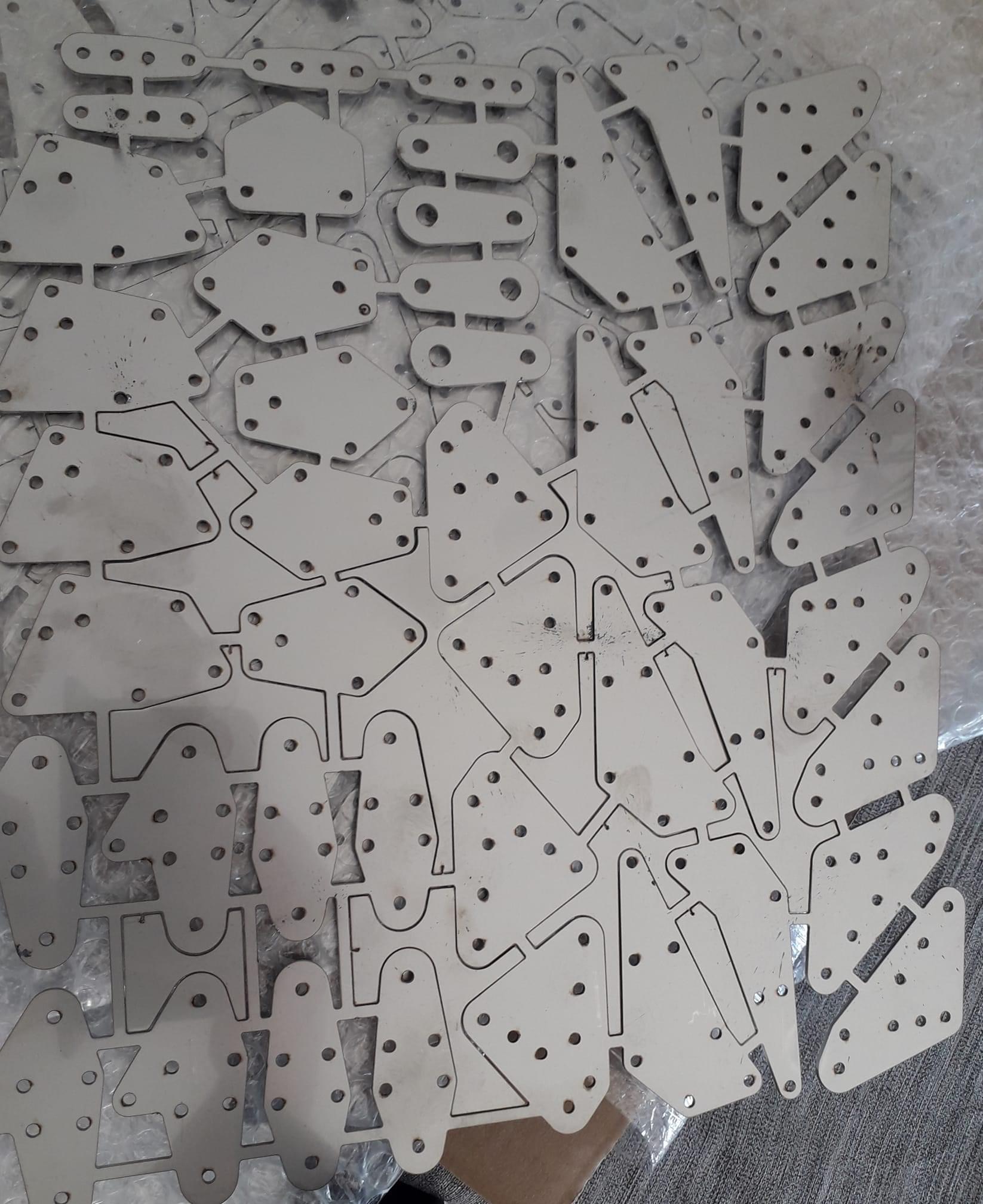
If in doubt do it the Paolo way 😉 . Success guaranteed!

cap-strips added

The full size cap-strips for the ribs are 1/4 x 1/4 pine. Scaled down that translates to 2.12 mm square. That is just too small for my fingers.

The plywood I have (that lite-ply) is 2 mm. I have nice 2 mm mill bits. (Not great for wood, but it works). Some time later, I have found The Way to Do it.

Mill a groove in the 11 mm strip, offset from centre (don’t ask where I got 11 mm, that’s what it is, came from some “Imperial” country. Supposed to be 1/2″), turn it around, same again, and last, run a deeper groove in the centre to cut it into 2 halves. Bingo, nice cap-strips.

Next I probably need to make a jig so I can glue the cap-strips on the ribs. (40 odd ribs.) en in general get busy. Once the glue dries, I can (if needed) sand the cap-strips down a bit, looking for no more then 3 mm wide. I’ll leave the height for now as is, it will give me some room to play with during the final assembly.

The vertical rib stiffeners are just scrap, probably do them in thinner ply. Joining the mains and aft spar requires triangular pine blocks, again, by the time you scale things down, they are small. I think I have a cone bit somewhere, I will try to make the blocks the same way as the cap-strips, mill a groove and chamfer the side..

Ouch, almost got myself in trouble. The cap-strips run all the way from LE to TE !! Even though the nose section of the wing is covered with plywood! Good to check, and check again. Which means I have to make the ribs complete, and slide them over the spars. No problem, but it shows you got to pay attention.

2 mm grooved cap-strips, can be sanded to size once glued to ribs.

making ribs

 Acroduster  Comments Off on making ribs
Jun 052020
 
trial wing ribs.

With the wing spars ready, it’s time to start thinking about the ribs. On these wings, nothing is straightforward, every rib looks different. (which gives it those nice wings 😉

Luckily the designer was smart enough to keep all the ribs up to the aft spar the same, so the only difference is the rear section of each rib. Which means, after I sorted the profile, I decided to make some test ribs to see how it all looks.

These are really just for testing, the wood is something called lite-ply, which to be honest is pretty useless. It’s as light as balsa, but warps by just looking at it. Been carrying it around for 20 years, so time to get rid of it!

The profile is approx 13%, I might thin it down slightly, I think 12% will still fit. It’s roughly a NACA0013, so 12 will do just fine. Or 12.6, or something.. I’ll think about it. Have to make sure the servo’s fit as well!

more small steps..

 Acroduster  Comments Off on more small steps..
Jun 042020
 
exactly 6 degrees bevel.

At some stage, after laminating the wing spars, I needed to bevel them at 4 degrees for the forward, and 6 degrees for the aft spars. Could have done it by hand, but this was quicker. (After spending 2 hours thinking about it, and trying to mount the planer. ) Only do this under adult supervision. You’ve been warned. Count fingers. Keep them.

Anyway, looks good. The main spars cut to length came at 97 grams each. That’s the great thing about wood, if it is too heavy, sand some more, until you get to your target.

Adult supervision required.
Lower wing attachment points.
starting to look like a bird…

There are some small errors in the laser-cut parts, but nothing that I can’t fix quickly. If I remember right, at one stage I thought that I needed a bit more material around holes, so added 0,5mm to the outer contour. Should not have done that, stuff is strong enough as it is! The rear attachment point is now a bit tight, but as I said, easily fixed.

Nothing like a good plan..

 Acroduster  Comments Off on Nothing like a good plan..
May 122020
 
..getting the right size and producing lots of shavings to get there.

After many thinking’s and deliberations, I came to the conclusion it would be better to build the bottom wings first. The mounting points are already fixed to the fuse, so their alignment is hardwired into the frame. When the bottom wings are done, I can align the top a bit easier.

I had planned on making the spars from sticks I have saved for 15 years now. They are vintage, but appear to be in good straight shape. These were once destined for a Waco project that never took off. There’s enough of them, and laminating thin strips gives a nice strong spar. Rear one is approx 26 x 7mm.

even a simple straight spar is not that simple!

I hope that having wings will make other parts easier. (famous last words.) The wing structure is going to be per full size, the hard way. The spars are what carries everything, and fore/aft stiffness is provided by 1″ alu tubing. The stuff that would be available is actually heavier then stainless steel, so I am going to use that. Which means I also need to make brackets for those tubes. And when I am at it, do all the other bits I need as well.

Glueing strips together is not that exiting, but this is the result.

seems the random alignment did not work out. Pay attention young man!

And for the rest, a bit of sanding and shaving to get to the correct size. I love the smell of pine!

Back to building

 Acroduster  Comments Off on Back to building
May 012020
 

I got a nice envelope of Bling last week. The process of getting from the parts I drew to something in my hands is not that complicated. Submit a dxf file, receive a quote, say yes, wait a few days, done. And the good part is, it is not breaking the bank!

The one thing that I had to learn is that a ‘part’ is a single dxf file. What you see here is a single file. Why is this important? The handling and preparation fees deal with single parts. There appears to be no limit to how complicated the parts is (apart from obviously the amount of time the laser needs to cut).

To keep it simple, stick as many individual bits together as you can, to produce as large a part as possible. That gives you the cheapest part. Unless of course you want a 1000 of each individual bit, but then we talk something else.

All I had to do is cut the bits apart, do a bit of filing and sanding an you’re done.

nice little puzzle

So next is doing some trial fitting, and start building the center section of the top wing. Once that is done, the cabane structure etc. At the moment there is a build thread on biplane forum, at just about the right stage. I’ll add some of these here for comparison

 Posted by at 6:42 pm  Tagged with:

Lining it all up

 Acroduster  Comments Off on Lining it all up
Feb 182020
 

Getting the cabane structure built was always going to be one of the challenging bits of the build. So, off we go. With the aid of my trusty 0.01 degree level, I’ve now lined up the fuse and a flat plate that will serve as the build-reference surface. As we speak, I just finished setting up the main center spar. Last week I bought myself a bandsaw from the interwebs. It was advertised as B-Ware, but since the price was right, I figured I probably could fix whatever minor ailment it suffered from. As it turned out, the power switch wiring had come lose inside the frame. I could fix that in about 5 mins. From the same lot I got a disc/beltsander. Also B-ware. The table in front of the disc had some boltholes drilled out of alignment. Yup, big job again. Clearing space for the toys took more time then the repair!

Which all leads up to: I need to cut some metal. I have asked for prices for laser-cutting the parts, but likely I can cut them just as well with the bandsaw. For which I of course need to locate the not so standard size saw. Luckily they can be made to order and do not cost the earth. (as in 15 Euro/pce, made in Germany.)

camera and lasers don’t go together..
fuse is at all the zero’s, now locate the main center spar.
Center spar, with printed attachment plate.
now I need to cut some real metal
 Posted by at 12:12 pm

TLAR (that looks about right)

 Acroduster  Comments Off on TLAR (that looks about right)
Feb 112020
 

That’s the way we used to (and still mostly do) design our stuff. If it looks right, it will fly right. Works since the days of the Wright brothers (and all those that went before and came after them.)

However, fun has to be had! I need to sort of start thinking about the wings in order to build the center section so that I can finish the pcovering of the front section. Given that the plans show a nice 1:1 rib, and given it is often stated to be a ‘Modified M6 profile’, I want to find out what Lou Stolp was thinking.

The short story: Take a picture, turn it into a black and white image, remove all noise, fiddle some more and import the result in Profili. Then say you want to find similar airfoils, job done.

It does not take long to come up with a list. We’ve got a NACA0013, a RAF30, a Goetingen 459 and an Ultimate profile, that all are very similar. Mix NACA0013 with RAF30 and you are 99% close to what Lou made. Running the results through XFoil shows characteristics that are somewhere between the 2.

note: on sheet 15 of the plans there is mention of a ‘osborne a-2’ airfoil. Can’t locate anything about it at the moment. (http://aerofiles.net/airfoils.html shows it, but no data. Jim Osborne was of course the guy who drew the plans 😉

full size profile drawing.

Before anybody asks: I haven’t got a clue what I am doing, but the curves look pretty! But I did have to go and find mr. Reynolds to figure out what I was looking at. (He says his number is somewhere between 300 and 500k for the speeds I guess this will fly.)

Given that the Ultimate is a known well flying Biplane, and the RAF30 profile is:

The basic symmetrical section ( R.A.F. 30 ) was calculated by the method described in R. & M. 911, using the constants k = 1.08, n = 1.95, B = 0. The aerofoil shape so obtained ends in a sharp angle, and so the last 1 percent of the chord was cut off in order to avoid a thin trailing edge. The form of the aerofoil was also adjusted slightly towards the trailing edge in order to remove a slight reflex curvature. The aerofoil has a maximum thickness of 0.13 of the chord at a distance of one third of the chord from the leading edge, and its shape approximates closely to the symmetrical Gottingen section 459 which was known to possess good aerodynamic characteristics.

Yup, that’s good enough for me..

In my younger days I did not have all this fancy stuff, I drew profiles that looked nice, and all those contraptions flew, so actually, this is just a fun exercise, that probably does not add anything to the overall results. But it looks good when you say you figured out what Lou Stolp did!

However, how we go from a M6 profile to a symmetric one remains a mystery for the moment. Searching some more I find this remark on kitplanes.com: The new airfoil is the RAF 34, which is similar to the M6 airfoil used on the Pitts. Searching for RAF34 on Airfoiltools.com indeed shows a profile similar to an M-6. The original Pitts did not have a symmetrical airfoil! Ok, happy with that. I’ll stick to what I have 😉

I could figure this out if I want to, but at the moment I’m not interested. I want a symmetrical profile, that is what I have, and how they got there is not really important.

 Posted by at 6:39 pm

A day figuring out the center section.

 Acroduster  Comments Off on A day figuring out the center section.
Feb 102020
 

Making the top wing center-section is a bit of a challenge. The drawings are not very clear. I started by making some fake parts, and see what makes sense. There is also no need for the wing-tank, which saves a bit of hardware. Given that the original construction was usually very clever, it pays to make things as the designer intended.

I also spend quite a bit of time digitizing the wing-profile, then trying to find an equivalent that is easy enough to make. Profile is very close to a standard NACA0013, so I will go with that. If I change my mind for a fatter profile, I need to adjust those plates below. A profile that came very close too is the one from an Ultimate. Either way, I’m close.

Some of the hardware for attaching wings to the centre section. The drawings provide a full size template. These plates are 4mm something strong enough. (1.5 mm Stainless will do fine)
purple is wing side, green bottom attaches to cabane struts. The pin is what holds it all together.
Grey tabs are connecting to the cabanes. This extra tab at the bottom of the blue part is the rear spar landing wire attachment point. The brown plates are extra plywood shims to prevent the wood of the spar splitting. Clever boys they were!

There are lots of notes on the drawings, several pages of part descriptions, but references are not always consistent, so lots of fun to figure this out!

But I think the method above should work. It’s drawn upside down. The main spar dimensions are 107 * 20 mm (yes folks, that is all!) scales down to 35 * 7 mm ( ’cause I found a stash of 7 mm rectangular pine sticks). Just needed to glue them together, and job’s done.

After this is all done, I can use this as a jig for building the cabane structure. Below is e real one. As you see the front attachment point is slightly higher then the rear one. As in it is a straight line offset from the center of the profile. It could also simply be to make life easy for the builders, because you need to have the attachment points parallel to the main frame top.

..a real life example.
 Posted by at 6:27 pm

Random stuff.

 Acroduster  Comments Off on Random stuff.
Feb 082020
 

Had some issues with the 3D-printer. Sometimes it would tell me the bed was not heating at the required rate and shutdown unceremoniously. Not Good. After the usual suspects were proven to be innocent it was the ntc resistor under the bed. Tiny as it is, it is a vital bit. Why oh why it would work for hours on end when I watch it, but throw a fizzy when I was not, is something only known to it’s designer. Anyway, after 4 years or so, it’s been retired. Since then, no more failed prints. So, to sensibly waste some plastic I quickly drew some parts for testing. Below you see a false former to support the front plating. Later the plating will be supported by the firewall. After my ABS adventures, I am now using ASA from FormFutura. (The light grey stuff). It has all the good habits from ABS, none of the bad. And indeed, shrinkage seems to be absent. This long part just fits the print-bed. With ABS I would not be able to print it without popping loose. (yes, this give me ideas for a future project 😉

false former for the front plating.
something to keep the driver busy.
Full size dimensions versus 1/3rd scale

And next.. Before i do the front paneling I need the cabane struts on the frame. Before that I need the hardware to mount it, so let’s see what I can cook up. This part is drawn full size on the plans. It is basically a bit of tubing (11mm diameter) with a 1.6mm sheet wrapped around it. This is really all that holds the top wings on the fuselage. For convenience I make mine from 4 mm tube (so I can use M3 bolts) and 0,8 mm sheet. I did some calculations, and if I am not too far of, that little thing can hold over 300 kg before it breaks apart. Actually, the weakest part is the soldered joint. Silver solder (worst case) has 300 N/mm2 tensile strength, the soldered area is 10 mm2. I think I’m safe enough with this.

The temptation is still there to make the tabs per full size, just need to find a method to keep things light enough and easy enough to fabricate. In fact, I don’t need to do the whole fuse, just this cockpit area… The method used at the tail end is way too difficult, mostly because I can’t source plain simple 2 mm strip..

Full size (image source: Biplaneforum.com)
or like this: a strip.

A nice in between job will be the throttle quadrant, and instrument panel.

I like this one, I can use some fancy displays for that!

Anyway, I guess I’ll have to build at a minimum a mockup of the center section, which means I need to think about the wing mounting.

All the images above are downloaded from BiplaneForum.com, I hope they don’t mind, and if they do, I am sure they will let me know 😉

 Posted by at 6:28 pm