
Had some issues with the 3D-printer. Sometimes it would tell me the bed was not heating at the required rate and shutdown unceremoniously. Not Good. After the usual suspects were proven to be innocent it was the ntc resistor under the bed. Tiny as it is, it is a vital bit. Why oh why it would work for hours on end when I watch it, but throw a fizzy when I was not, is something only known to it’s designer. Anyway, after 4 years or so, it’s been retired. Since then, no more failed prints. So, to sensibly waste some plastic I quickly drew some parts for testing. Below you see a false former to support the front plating. Later the plating will be supported by the firewall. After my ABS adventures, I am now using ASA from FormFutura. (The light grey stuff). It has all the good habits from ABS, none of the bad. And indeed, shrinkage seems to be absent. This long part just fits the print-bed. With ABS I would not be able to print it without popping loose. (yes, this give me ideas for a future project 😉
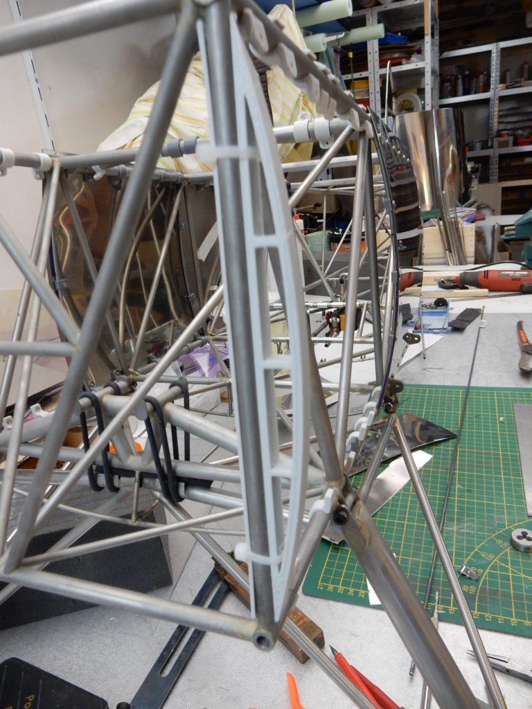
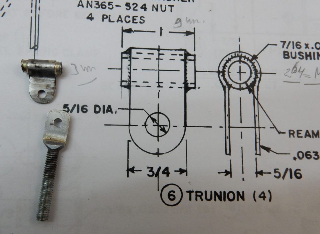
And next.. Before i do the front paneling I need the cabane struts on the frame. Before that I need the hardware to mount it, so let’s see what I can cook up. This part is drawn full size on the plans. It is basically a bit of tubing (11mm diameter) with a 1.6mm sheet wrapped around it. This is really all that holds the top wings on the fuselage. For convenience I make mine from 4 mm tube (so I can use M3 bolts) and 0,8 mm sheet. I did some calculations, and if I am not too far of, that little thing can hold over 300 kg before it breaks apart. Actually, the weakest part is the soldered joint. Silver solder (worst case) has 300 N/mm2 tensile strength, the soldered area is 10 mm2. I think I’m safe enough with this.
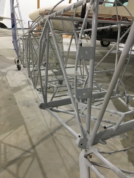
The temptation is still there to make the tabs per full size, just need to find a method to keep things light enough and easy enough to fabricate. In fact, I don’t need to do the whole fuse, just this cockpit area… The method used at the tail end is way too difficult, mostly because I can’t source plain simple 2 mm strip..
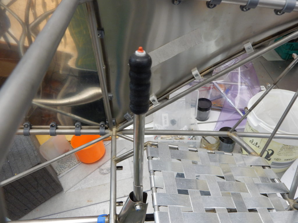
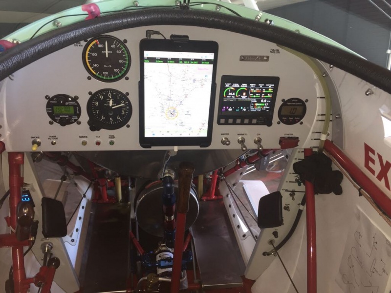
A nice in between job will be the throttle quadrant, and instrument panel.
Anyway, I guess I’ll have to build at a minimum a mockup of the center section, which means I need to think about the wing mounting.
All the images above are downloaded from BiplaneForum.com, I hope they don’t mind, and if they do, I am sure they will let me know 😉