
3 reasons, Ed asked my if I could do something for his latest project, and I really fancy those 1970’s looking flared undercarriage pants as well. So, bite the bullet, and do some thinkings. I found what appears to be a good starting point on github, so let’s see if we can do this. The greatest hurdle for me is the design phase, once I have the .stl file it’s simple.
The 3rd reason is that I am knackered from working in the garden today, SWMBO decided that the path that runs around the garden needs moving.
The program as is does allow multiple profiles sections, but it does divide then equally along the span. Not what I need. So we have two options, fix the code, or make the pants into multiple sections. The first method will require brain-cell activity, we go with that!
28 sept: It’s a bit of a slow week with other jobs taking priority, but things are progressing. Taking the road less traveled is definitely keeping the braincell entertained. I learned a lot the past few days. I managed to get the turtledeck drawn, and I thought it was then only a matter of printing. Oh the folly of innocence..
..so what is the challenge? When I import the .stl the ‘skin’ is either to thin, so that the printer does not see it. (less then the 0.4 mm orifice of the printhead.), or if I make the part thicker is starts to complain in a language I do not want to repeat..
/*
Construction of the turtledeck for the SA750.
Date: 28 sept, 2019
Inspiration: https://openhome.cc/eGossip/OpenSCAD/lib-bezier_surface.html
OpenSCAD 2019.08.04
All rights as usual, do as you please, it's open source.
*/
include <bezier_curve.scad>;
include <bezier_surface.scad>;
include <function_grapher.scad>;
t_step = 0.01; // smoothness, might be too much for real life printing.
thickness = 0.1;
width = 0.1;
inch=25.4; // is an inch
scale=0.33; // my scale
// refer to fuse stations on full size.
sta75= 0;
sta100=25*inch*scale;
sta120=45*inch*scale;
sta125=50*inch*scale;
sta129=54*inch*scale;
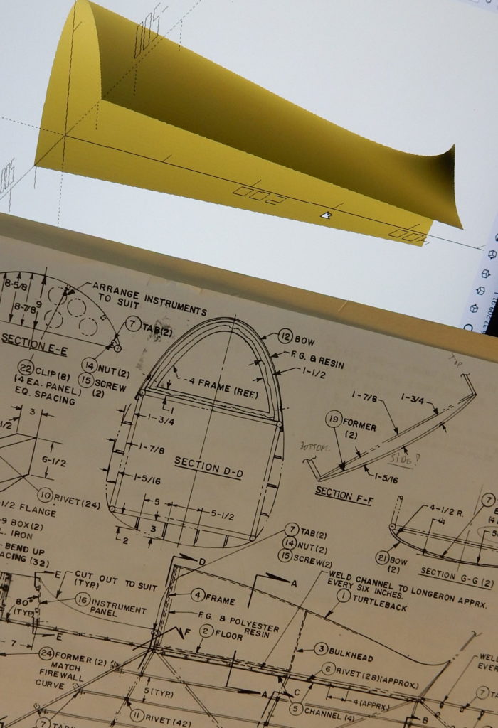
/*
Draw the approx formers on a piece of grid paper, and take the coordinates from there.
*/
formers = [
//former at sta75
[[-109,0,sta75],[-100,36,sta75],[-80,82,sta75],[-60,105,sta75],[-40,124,sta75],[-20,136,sta75],
[0,140,sta75],
[20,136,sta75],[40,124,sta75],[60,105,sta75],[80,82,sta75],[100,36,sta75],[109,0,sta75]],
//former at sta100
[[-75,0, sta100],[-60,55,sta100],[-40,92,sta100],[-20,105,sta100],[-10,120,sta100],
[0,150,sta100],
[10,120, sta100],[20,105,sta100],[40,92,sta100],[60,55,sta100],[75,0,sta100]],
//former at sta120
[[-55,0,sta120],[-30,30,sta120],[-20,43,sta120],[-10,46,sta120],
[0,50,sta120],
[10,46,sta120],[20,43,sta120],[30,30,sta120],[55,0,sta120]],
//former at sta125
[[-44,0,sta125],[-30,30,sta125],[-20,43,sta125],[-10,46,sta125],
[0,50,sta125],
[10,46,sta125],[20,43,sta125],[30,30,sta125],[44,0,sta125]],
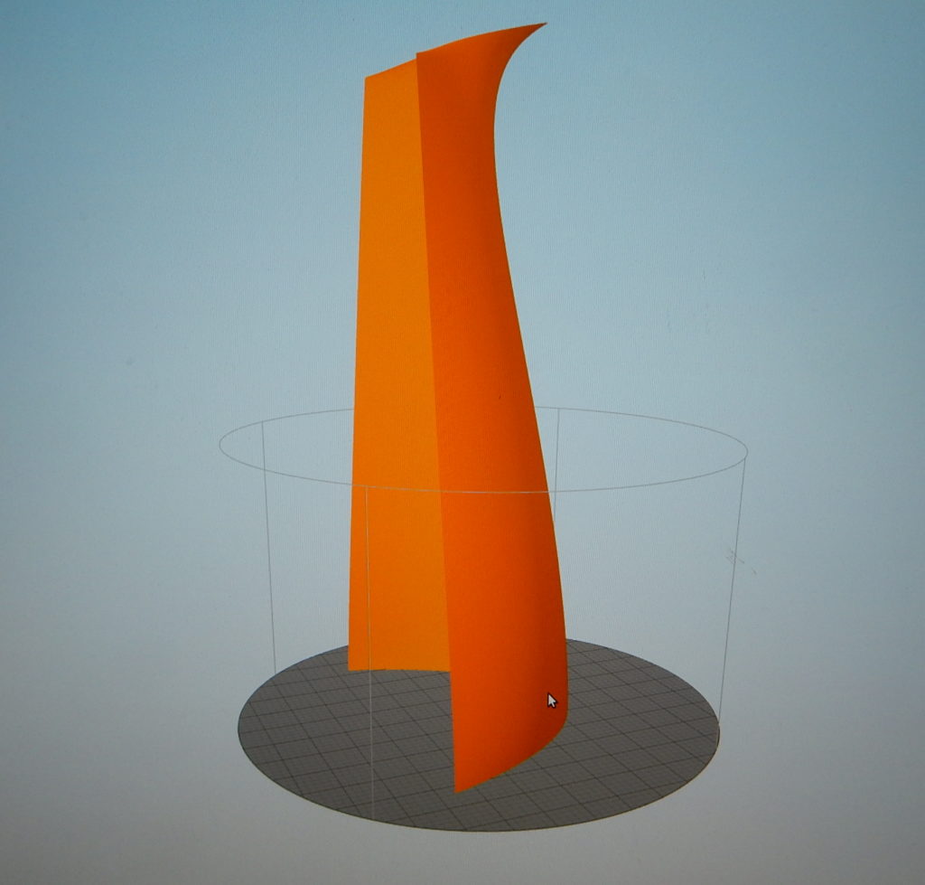
// and a fake one to get the rudder blended in.
[[-44,0,sta125],[-30,20,sta125+6],[-20,30,sta125+12],[-10,40,sta129-14],[-5,65,sta129-6],
[0,250,sta129+inch],
[5,65,sta129-6],[10,40,sta129-14],[20,30,sta125+12],[30,20,sta125+6],[44,0,sta125]],
];
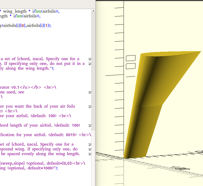
//here the magic happens.
function_grapher(bezier_surface(t_step,formers),thickness);
// that's all there is to it. (if only!) If only I had the knowledge I will have in 5 years today, this would be easy.After a lot of pulling the hairs, I got the code down to the above, it works beautiful and it ‘should’ be simple to build other variants, if, but only if I can get the code to play happy with the printer. I normally slice with Simplify3D. Since I have Octopi (cura slicer) running on the printer, I want to try if that will eat it.
The other slight issue is of course that I will have to chop up the part in 2 or 3 sections, but that should not be a problem. In the end it will be covered with a layer(s) of light glass to keep it from falling apart. The whole idea is of coarse, that modelling in software is ”easier” then producing lots of dust.
That’s the theory..
29 sept: after a good nights sleep I woke up to realize I have a lot of the good stuff from Stefano. Why oh why did I not think about that? The other option is to try with Freecad, import the .stl, make it a solid and take it from there. Options, options. Then there is Solvespace, and of course all the paid for stuff that I can’t afford.
30 sept: ok, this is the reason why this does not slice well: the code likes the shape to bend in certain direction. At the tail end I try to be smart and diverge, creating a bend in the other direction. And that is what is causing the problems for the slicers.