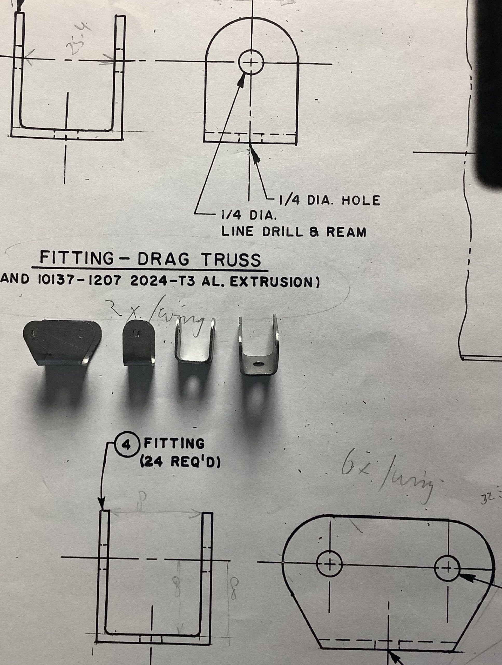
Finally getting the hang of producing chips in a consistent way. I think I need approx 36 pcs of the brackets you see in the second image. By the time I have those made, I’ll be an experd.
These by the way are fittings for truss-tubes in the wings. Once the wings are covered nobody will ever see them again.
Below is an image from the build process of a full-size version. The red tubes are 1″ diameter, the bolts at the bottom of the image are 1/4″ (6 mm)
All that stuff is not that big!
Brackets can be seen where red tubes connect. My version of the brackets.
Arduino, JetiComments Off on Just another relaxing day
Sep292020
I finally reached D-Day (Departure-Day) and have been taking it easy the last few weeks. Easy as in not spending time on modelling activities, but more time on ‘Life’ things. But, since a few days, Autumn seems to have arrived, so a good time to warm-up the soldering iron to keep the man-cave warm.
One of the things I needed to sort out was a flow meter for a Glider-Tug. Since a Flow-meter is just a lonely thing on it’s own, I decided to add a RPM sensor, and for good measure, a GPS. That makes it now a pretty good unit for Tow-planes.
Anyways, before you ask, I did not write the code to make it all work, just the usual tweaks to make it do what I want. Thanks goes to Thomas Lehmann for his excellent code.
only requires minor assembly..
Which leaves me to glue a few parts together. One of the lessons learned is that you really need to have a decent stable 5 Volt supply on your Arduino. Which means you need to feed it from a regulator thingy. I did use step-down regulators in the past, but especially around 5V input things did not always work as designed. Anyway, long story, I found some Buck-Boost regulators, that allow a wider range of input voltage, while keeping the output where it has to be. (and yes, this one is slightly different form the advertised one. Did I say no 2 parts are the same? Anyway, it does the same trick, so all is good.)
The regulator is rated for 600 mA, the total current for the unit is about 25mA, so well within specs. Input is max 12V.
One other Thing to keep in mind: most Arduino Pro Mini’s now are advertised as a ‘5V’ part. All it means is that the input voltage (VRaw) is supposed to be 5V. The onboard regulator drops that down to 3.3V (Vcc) . And when you then connect all your 5V sensors to the usual places, you can have a fair idea why things don’t work.
..fiddly stuff those smd resistors.
The Atmel328 on this board has 5V tolerant inputs, so it is safe to connect the RPM sensor directly to the input pins, same goes for the Flow meter. The flow meter also needs a minimum of 5V to operate.
Just for fun I’m printing a new box, life would be boring if I used what I had already.
GPS at the Top/Bottom, there’s even an arrow on the box to show which way the sky is. ..keep tuning the printer settings, think I’m slightly low on volume on the surface.
The only niggle I have at present is that the good people who sent me the flow-sensor, advertised it to include a connector. Someone must have borrowed it, because there ain’t none. I found an old 2S Lipo in my box of tricks and ‘borrowed’ it’s connector. Problem solved.
Next step, make some new PCB’s to replace the ones I got from Thomas. Those were designed for a slightly different Arduino. As with all these things, no 2 orders will give you the same parts. This is a general purpose board to which you can connect all the possible sensors that the software supports. Handy if you want to build 100 pcs, I don’t want to make that many! Given that the above assembly is so little work, the effort to make a new PCB is more for learning a new trick than anything else. As many times before, the software I used to work with is no longer available, it is replaced by something better.
All that’s left is to make the sensor cables, that should not take long.
Looking back a few posts make me think maybe I should add the airspeed sensor too. I did have some flights with it, but I need to get a much smoother display then I have at present. The sensor produces an analogue voltage, which fluctuates way too much. Filtering is needed, how much is a matter of mostly trial and repeat.
I’ll save that for the next one!
And see if I can make a totally optically isolated version. That would be handy too.
Next one after the next one. Maybe.
Do remember to change the MS5611.cpp in the linked library to fix the problem with MS5607 sensors! (for now, if I don’t get any more of these funny ones, I’ll let it be.) Or try to modify the main code to pick the modified library.
So for the next one I will remember which connector goes to what sensor!One in the making, one ready to fly
So, enough on this subject, time for something else!
In the summer of 2020 I had the idea that I wanted to let full size pilots know where we are flying. There is no easy way to do that. But then I found the Open glider Network. What started out as a ‘just for fun’ project, turned into something that I don’t want to fly without anymore.
In Dec 2020, I encountered a heli-driver, going full speed straight across our field at less than 300 ft, where I was a few minutes earlier.
Onglide Range (to see if my antenna works.) The first day I had the antenna (home bent) on the roof, looking south, I was lucky enough to track a photo-plane. (D-IAPD) This gave me a good lot of information as to the performance (more lack-there-of at the moment).
First I build a OGN-Groundstation, and was lucky enough for someone to keep flying nearby.
Thank you D-IAPDand then he went home ..
In short, the photo-plane had connections to the Gorinchem node. (The fellow has a good 9 dBi antenna mounted above rooftop.) and to other stations more then 100 km away. Since the signals really depend on line of sight, you can bet they are higher up then I am! I already noticed that the Eltenberg is in my way 😉
Long story short, if you want to play you need a 9 dBi antenna. Yikes.. Hard to beat, but there’s no fun without a challenge!
First impressions (antenna way too low!) this plane was tracked to 12 km, when I had a good 10 dB signal. You can have good data to as low as 0.8 dB, if you can see the plane! so hopefully that part will be rectified RealSoon.
When I am higher, I can start playing with the antenna design. (FYI, all this 868 Mhz stuff is also applicable to 2.4 GHz systems. See where I am going?) No better way to learn then try to create and solve your own problems!
Let’s also say that apart from several air-plane types that are tracked, there are: Obstacle and UFO. I’ll forget the UFO for the time being, but Obstacle could be interesting. Park an obstacle at our field and the big boys should take notice!
Of course this is not something you do, just for fun, much discussion will have to follow. But imagine the future, when the whole world has their pizza delivered by drone, you can put an obstacle in your backyard and say: not in my backyard!
Yes, this all has to do with the regulations being forced upon us. Better to know and understand then to wake up one morning and find out we’ve been administratively cleansed!
So no cutting of metals this week? Yes/no/working on it. I never quite got the ancient software to play nice when cutting layers. In wood that don’t matter too much, in metal, things start to smoke or bend. working on it!
Anyways, it’s hot outside, still 30+C at 20:00. I’m calling it a day!
What took you so long? No idea.. More then 10 years ago I got myself a CNC-router with the idea that I would be able to metal metal parts. I’ve used it up to now mostly for non-metal parts. But retirement has given me enough time to finally sort things out. That and a better understanding of materials, cutting speeds etc. And after the smokies I had here, this is much better!
So, here we are: first part. This is a bit of steel which should probably not have that name. It cuts like butter, which is good for my confidence!
first part that was not produced with smoke and fire!need to make a better jig, but the idea works. and the final part.
The observing reader will notice that my hole sizes are off. Original is 6 mm bolts, scaled would be 2 mm. I feel that’s a bit thin. I’ll use standard 3mm ones , marked 8.8= 800 Newton/mm2.
M2, core area is 1.8 mm2. 1.8 * 80 =144 Kgf.
M2.5, core area is 3 mm2. 3.0 * 80 = 240 Kgf
M3, core area 4.5 mm2. 4.5 * 80 = 360 Kgf.
(not sure I have the right table here, check later! Values feel about right though) See here and this one
Ok, I’ll drill them 2.0 for now, looks like that is really enough. I’ll leave the one going through the spar at 3 mm, makes life easier. Yeah, I know, you should sort this out BEFORE cutting metal. Me thinks I’m due for a coffee break!
Trying with 0.6 mm stainless steel. It’s shiny, no other identification. Problem 1: it does not stay down on the board very well, so I really need a DOWN cut bit. (learned that in a hurry!) Not to be stopped that easy, I went slow, lots of cooling fluid, and managed these 2 parts. Progress is being made by counting the bits that did not work. Also, because the sheet is not fixed properly, I get some chatter, visible on the edges and general outline. All to be expected and just needs time to fix. I think it would also be better to have the cooling nozzle fixed to the head, moving around by hand as we go is possible, but not great.
Finally got the airspeed sensors, so what better to do on a rainy afternoon them to play with them? First the specs: Datasheet, and a picture. Bear in mind that all these diy chips are basically old stuff. This one dates from 2012. Obviously nothing wrong with them, they are still used in a lot of equipment, but they are not the smallest of parts! However, this makes it so easy for us diy-ers to play with them.
which tube goes where.
The metal probe weighs approx 10 gram, with electronics, housing etc, ca 40 gram. (too much cabling, and unwanted plastic). I don’t want to stick that on the tail of a glider yet. I’ll use that on the wingtip of the Carden. ( I think, maybe, or something). Easiest for testing is to connect the sensor to the input of my JetiBox. (I think this can be done) and stick it on the car. We’ll see where this goes.
Some how the Jetibox only displays 14 sensors, (supposed to be 16) and most of them are for the GPS that is not present and disabled. I guess I have to ‘fix’ the software for this. Can’t think of another way at the moment.
The sensors-information must be stored along with the Rx identity in the JetiBox. (Not in the transmitter, in the JetiboxProfi box thingy.) Good project for another rainy-day, because I suggested to one of our BigGlider guys that I could use this to monitor ‘from the side’ if and when he has signal dropouts. I can do it at the moment, but I would still like to see the airspeed at the same time. That was the idea behind the stand-alone system. Stick it on anything, and monitor from Jetibox. Actually, with all the sensors on board you could monitor lots of things, without having to interfere with the electronics of the plane. (Fokker-E3 rings a bell, what speed is it really moving, and would it not be nice for it to complain when things are getting dicey. Just a thought…)
sort of prototype, just enough to keep things in place
Wingtip? If I add a small 2s 150mAh lipo it will be a completely self contained, stand-alone unit, that is connected to the DS-14. Weight is easily added to the opposite tip to balance things. That, or stick it an the rudder, the Carden won’t mind so much. Much fun to be had!!
And in the meantime, our friends delivered a bunch of cutters for the CNC-machine and some parts for making a mist-cooling system. As always, the general idea is present, the execution is still to be puzzled out. Where do I put stuff?? On the router head so it moves along with stuff I cut, (wishful thinking) , or nail it to the bottom and for the few small parts I have to make it is ok to simply spray enough the centre of the part. And I need some cutting fluid. Look for local cutting fluid, and start doing it!
This series has an extra voltage regulator, I have a feeling the version that runs straight on the 5V from the receiver is a bit too sensitive to voltage fluctuations. These ones are to be fed from a 2S Lipo or LiFe supply.
Arduino, JetiComments Off on 1012 mBar in the shed.
Jul102020
Continuing with the Barometric Pressure Sensor saga. Here are the data sheets for the MS5611, and the MS5607.
The parts that show the different methods for calculating pressure and temperature are highlighted in the images.
MS5611 MS5607
Use the linked datasheets if you can’t read the fine print.
M5611 MS5607
Crudely changing the code at least gives me good results now! Next is trying to merge this in the VarioGPS code. One way to do it is to use the chip-select bit to determine which chip.
I2C INTERFACE COMMANDS Each I2C communication message starts with the start condition and it is ended with the stop condition. The MS5607-02BA address is 111011Cx, where C is the complementary value of the pin CSB.
Pulling it high will give an address of 0x76, (normally pulled to zero by 2k2, gives it a 0x77 address.) VarioGPS already uses this trick to identify another chips. I might ‘simply’ put the MS5607 in that slot, since I don’t have that chip.
Memory is already tight, so I removed both the LPS and BMP280/BME280 sensors. That gives me enough room to play and get the code inserted and cleaned up. I can always stick it in later when/if things are working.
RAM: [===== ] 50.5% (used 1034 bytes from 2048 bytes)
Flash: [========= ] 91.6% (used 28144 bytes from 30720 bytes)
I received some chips last week, they are to be used in a VarioGPS unit for Jeti. I’ve build around a dozen of these things now, and so far I have had no real issues. So what happened?
As always with stuff from ‘the east’ you never know what you get. But I am jumping ahead.
With a fresh cup of coffee and a hot soldering iron, fun is to be had. First load the firmware on the Arduino-Nano. Yup, done that a million times. Only this time my usb cable is bad. Ah well, after last weeks mains cable to the router spindle, what is to be expected? Somebody trying to keep me on my toes? Anyway, carrying on regardless. Code loaded, and the first one assembled. No GPS reading? And the air pressure is only 507 hPa? (Exactly half what it has to be.)
Ok, back to basics. Of the 10 GPS modules (them expensive ones) 9 are good, the one I used is bad (for now, maybe I can revive it).
But that altitude problem turns out to be a Real Good one!
The Barometric Pressure Sensor chips that are mounted on the GY-63, as these boards are called, is normally a MS5611. (I used this link for reference, this is NOT where I got mine!!) Everybody uses them, no problems ever reported. They have a resolution of 10cm.
When I finally was able (with 3 magnifying glasses stacked) to read what was on the chip, it said: MS560702BA03. I received MS5607’s that are advertised as MS5611, but obviously they are not!
They are the predecessor of the MS5611, and an obsolete part. And the Big, Really Real Big Problem is, that they have half the resolution. (20 cm). Now, resolution would not necessarily be an issue. Range is the same, all other specs are the same, the code according to the manufacturer is the same.
Looking at many available (Arduino) libraries, you only see the occasional statement that the library is MS56xx compatible, meaning good for both MS5611 and MS5607 (and others).
So, what next? As always I am a sucker for getting to the bottom of the problem, and a $5.00 chip ain’t getting the better of me. But it is annoying to pay for a premium part and get a shitty one. We’ll see what our friends say about it.
My solution for the time being, is to change the code! (What else?)
// code from the manufacturers application note
// https://www.amsys-sensor.com/downloads/notes/MS5XXX-C-code-example-for-MS56xx-MS57xx-MS58xx-AMSYS-an520e.pdf
This bit is from the application note.
D2 = cmd-adc (CMD_ADC_D2_CMD_ADC4096); //read D2
D1 = cmd-adc (CMD_ADC_D1_CMD_ADC4096); // read d1
dT=D2-C[5]*pow(2,8); // D2-C[5] * 256
OFF= C[2]*pow(2,17)+dT[4]/pow(2,6);
SENS=C[1]*pow(2,16)+dT*C[3]/pow(2,7);
T=(2000+(dt*C[6])/pow(2,23))/100; P=(((D1*SENS)/pow(2,21)-OFF)/pow(2,15))/100;
The code below is used in the MS5611 library, file MS5611.cpp
*/
{ uint32_t D1 = readRawPressure();
uint32_t D2 = readRawTemperature();
int32_t dT = D2 - (uint32_t)fc[4] * 256;
int64_t OFF = (int64_t)fc[1] * 65536 + (int64_t)fc[3] * dT / 128;
int64_t SENS = (int64_t)fc[0] * 32768 + (int64_t)fc[2] * dT / 256;
if (compensation)
{ int32_t TEMP = 2000 + ((int64_t) dT * fc[5]) / 8388608;
OFF2 = 0;
SENS2 = 0;
if (TEMP < 2000)
{ OFF2 = 5 * ((TEMP - 2000) * (TEMP - 2000)) / 2;
SENS2 = 5 * ((TEMP - 2000) * (TEMP - 2000)) / 4;
}
if (TEMP < -1500)
{ OFF2 = OFF2 + 7 * ((TEMP + 1500) * (TEMP + 1500));
SENS2 = SENS2 + 11 * ((TEMP + 1500) * (TEMP + 1500)) / 2;
}
OFF = OFF - OFF2;
SENS = SENS - SENS2;
}
//uint32_t P = (D1 * SENS / 2097152 - OFF) / 32768; // 507 hPa, readout is exactly half what I expect.
uint32_t P = (D1 * SENS / 2097152 - OFF) / 16384; //
return P;
}
/* Fudging the result for now by dividing the last line by 16k instead of 32k fixes the result, but not the cause.
It’s bad, it’s fixing a hardware problem with a software fudge. But hey, it kept me busy for a few evenings, and that braincell certainly got a tune-up!
The recipe for calculating the pressure.
My RPM meter for the spindle? working really good. And surprisingly accurate and stable. RPM’s on the Kress 800 are from 10000 to just a shade under 29000. I even printed a box for it, so that the fingers do not get in the way of sharp things. Since usually it is a mess near the spindle, with all kinds of stuff flying around, I decided to keep it as a separate unit. If I need to set a RPM, I can do so easily before cutting. And yeah, I ordered better cutting bits. By the time I have all this finished I could have shaped 100 parts by hand, but there’s no fun in that 😉
Yeah, the spindle problem: turned out the the constant flexing of the mains cable killed the cable. Took 10 years, so I’m not complaining. All is happy again, and the spindle even sounds better. Which probably leads me to another project: Do I upgrade the Router to modern electronics/software or carry on as is? Will it make life easier? Will it make coffee? (Just in case I run out of things to do, one needs to have things lined up!)
update @ 2200: found the differences between the sensors. Testing next..
I wanted to use this nifty little display for my RPM display of the spindle on the CNC-Router. It somehow switched to a 128*32 mode.
Digging in the code, I found a problem (for me, in this sketch) Activating the 128*64 define in Adafruit_SSD1306.h library, fixed it.
Yes, of course, it (they) will go into the plane as well, that’s why I got them 😉
/*!
* @file Adafruit_SSD1306.h
* This is part of for Adafruit's SSD1306 library for monochrome
* OLED displays: http://www.adafruit.com/category/63_98
* Written by Limor Fried/Ladyada for Adafruit Industries,
*/
#ifndef _Adafruit_SSD1306_H_
#define _Adafruit_SSD1306_H_
// Note: my display only showed 32 lines,
// changing this define to the one below
// cured the problem. Standard 'define SSD1306_128_32' is wrong.
// Kees Blokland, 2 July 2020
// ONE of the following three lines must be #defined:
#define SSD1306_128_64
//#define SSD1306_128_32
Update: The better and proper way is to add the directives from the updated library in the source code:
Adafruit_SSD1306 display(128, 64, &Wire, 4); // This forces 128*64 display and a reset. Before it was:
Adafruit_SSD1306 display(4);
So the display is working, but values are jumping around too much. This is a known arduino limitation, and somewhere I have a library from ElectricRCAircraftGuy that solves the problem to a large extend.
Oh, and in the meantime the router motor has decided to stop. It did sound funny lately, more work! Usual case of ‘last night it worked, today it does not’. Using a Dremel for creating revolutions to count.
Yes the shed roof is still being worked on too, and so is the garden, and a myriad of urgent stuff…
For the first time in months it’s raining today! Just checked my rain tanks, they are filling slooow, the plumbing is ok, no leaks. (Trust me to install rainwater capture tanks, and then it does not rain for months!)
Challenge of the day: I really, really want to make these small metal parts myself. Problem I have is not Knowing Enough about milling speeds. (Not knowing anything about cutting metal is probably closer to the truth).
Truss drag fitting: result in 0.5 mm mild steel.
So when I tried to cut some stainless steel I get a red hot milling bit, with sparks flying everywhere. That, my friend, is NOT GOOD. I already went down to the lowest speed my spindle runs (10k), slowest feed (30mm/min) lowest plunge depth (0.5mm). I have a 2 mm 3 flute bit in my Kress 800.
What now? I know about cnccookbook.com, but the GWizard software only runs on a Windowz system. ;-(
Anyway, installed a trial version of GWizard on the work-laptop (which I will not use for work anyway) and plugged in the numbers I used. Well, lets say it recommended I do not try this at home!
What should I do next? Get better and more suitable mills is the obvious answer! Stuff that works for plywood, does not make a good metal cutter. But first let’s see what I have. I have a bunch of short 1 mm cutters. Long story short, I need a higher feed-rate and lower RPM. Easy said. Now try to make that router behave. Since it’s raining, some good Irish country music playing in the back, lets tackle it!
After some googlings I think I found bits similar to what I have. The company that mine came from 10 years ago, does not have a search function on their website. Going through loads of pdf books is a bit too much fun today.
mine are not AlTiN coated, I should use lower speeds I guess.
First we needs something to actually measure spindle RPM. I am sure I have an prop-rpm gadget somewhere. But ‘Somewhere‘ is a bit elusive at present, I’ll try to remember where I put it. Can’t find it….
with all the happy numbers plugged in.
Playing around a bit more, I can actually use the 2 mm HSS mill that I have mounted now, needs 60 mm/min @ 5300 RPM, cutting depth is 0.5mm, slot width =2 mm
I did find some of my old reflective sensors, so we are almost done. (famous last words). Fire up the soldering iron, and cook up some code.